High-power ultracapacitor energy storage pack and method of use

Inactive Publication Date: 2006-08-01
SHEPPARD MULLIN RICHTER & HAMPTON +1
View PDF19 Cites 39 Cited by
  • Summary
  • Abstract
  • Description
  • Claims
  • Application Information

AI Technical Summary

Benefits of technology

[0013]Another aspect of the invention involves a method of using an ultracapacitor energy storage cell pack including the steps of providing an ultracapacitor energy storage cell pack including a ultracapacitor assembly having a plurality of parallel ultracapacitors and balancing resistor in series, each balancing resistor in parallel with each ultracapacitor to automatically discharge each ultracapacitor over time, thereby balancing the ultracapacitors of the ultracapacitor assembly and assuring a safe condition for service personnel; an enclosure to enclose and protect the ultracapacitor assembly; a controller for the ultracapacitor assembly; one or more temperature sensors to monitor temperature of the ultracapacitor assembly and coupled to the controller; a pack voltage sensor to monitor voltage of the ultracapacitor assembly and coupled to the controller; a GFI sensor to monitor for a ground fault interrupt condition of the ultracapacitor assembly and coupled to the controller; one or more cooling fans carried by the enclosure and controlled by the controller to cool the ultracapacitor assembly based upon temperature sensed by the one or more temperature sensors; an on/off relay coupled to the ultracapacitor assembly and the controller, the on/off relay activated by the controller during normal operation of the ultracapacitor assembly and deactivated by the controller wh

Problems solved by technology

However, the chemical reaction that occurs internal to a battery during charging and discharging typically limits deep-cycle battery life to hundreds of charge/discharge cycles.
This characteristic means that the battery pack has to be replaced at a high cost one or more times during the life of a hybrid-electric or all-electric vehicle.
Batteries are somewhat power-limited because the chemical reaction therein limits the rate at which batteries can accept energy during charging and supply energy during discharging.
In a hybrid-electric vehicle application, battery power limitations restrict the drive system efficiency in c

Method used


Image

  • High-power ultracapacitor energy storage pack and method of use
  • High-power ultracapacitor energy storage pack and method of use
  • High-power ultracapacitor energy storage pack and method of use

Examples


Embodiment Construction

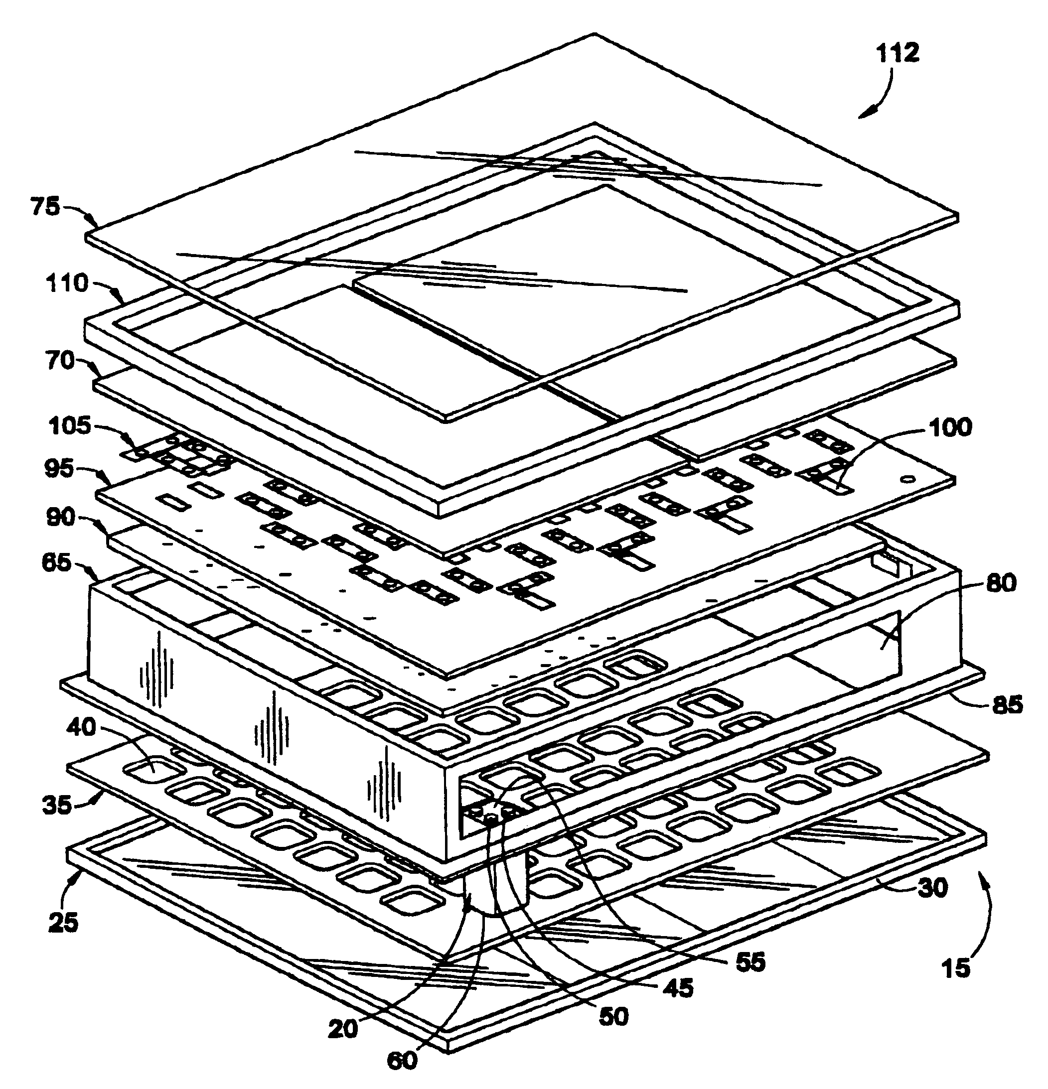
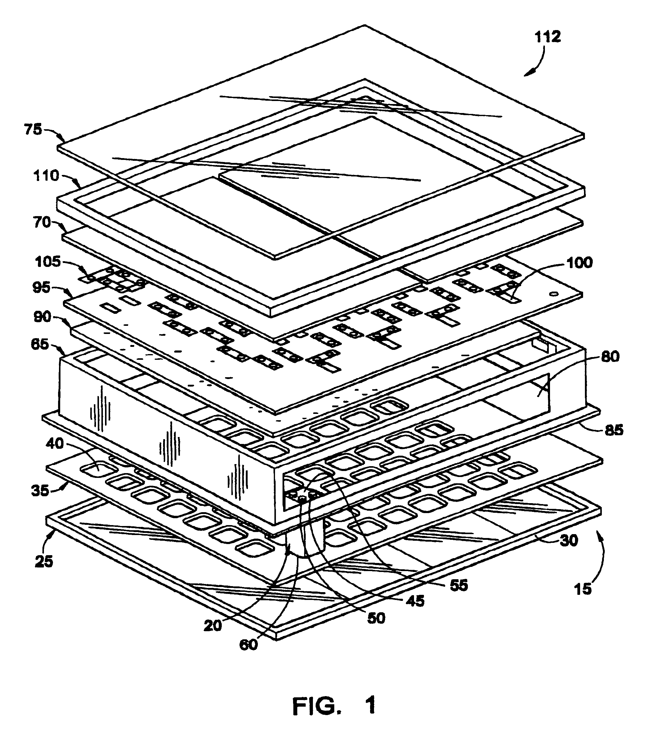
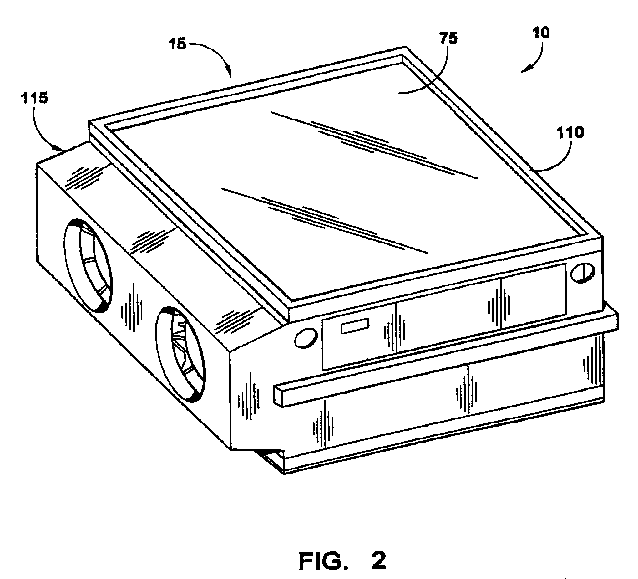
[0023]With reference to FIGS. 1 and 2, an embodiment of an ultracapacitor energy storage cell pack 10 will now be described. FIG. 1 illustrates an exploded view of an embodiment of a half module 15 of the ultracapacitor energy storage cell pack 10. FIG. 2 illustrates an embodiment of an assembled ultracapacitor energy storage cell pack module 10, which includes two half modules 15 fastened together. Although each half module 15 preferably includes eighty ultracapacitors 20, each half module may have other numbers of ultracapacitors 20. Further, the ultracapacitor pack 10 may have other numbers of modules 15 besides a pair (e.g., 1, 3, 4, etc.).

[0024]The ultracapacitor pack 10 is shown in exploded view in FIG. 1 to illustrate the different levels in the half module 15 that are added during assembly of the half module 15. Each of these levels will now be described in turn below followed by a description of the assembly process.

[0025]An aluminum base plate 25 forms a bottom or inner-mo...


PUM


Abstract

An ultracapacitor energy storage cell pack includes an ultracapacitor assembly including a plurality of parallel ultracapacitors and balancing resistors in series; an enclosure for the ultracapacitor assembly; a controller; one or more temperature sensors; a pack voltage sensor; a GFI sensor; one or more cooling fans carried by the enclosure; an on/off relay coupled to the ultracapacitor assembly and the controller, the on/off relay activated by the controller during normal operation of the ultracapacitor assembly and deactivated by the controller when the GFI sensor detects a ground fault interrupt condition, the one or more temperature sensors detect an over-temperature condition, or the pack voltage sensor detects an over-voltage condition; and a pre-charge resistor and a pre-charge relay coupled to the ultracapacitor assembly and the controller, and activated by the controller to cause the pre-charge resistor to limit pack charge current until the ultracapacitor assembly reaches a minimum voltage.

Description

CROSS-REFERENCE TO RELATED APPLICATIONS[0001]This patent application is a continuation-in-part application of U.S. patent application Ser. No. 09 / 972,085 filed Oct. 4, 2001 now U.S. Pat. No. 6,714,391.FIELD OF THE INVENTION[0002]The field of the invention relates to a high-voltage, high-power ultracapacitor energy storage pack composed of a large number of serially connected individual low-voltage ultracapacitor cells that store an electrical charge.BACKGROUND OF THE INVENTION[0003]The connecting together of individual battery cells for high-voltage, high-energy applications is well known. However, the chemical reaction that occurs internal to a battery during charging and discharging typically limits deep-cycle battery life to hundreds of charge / discharge cycles. This characteristic means that the battery pack has to be replaced at a high cost one or more times during the life of a hybrid-electric or all-electric vehicle. Batteries are somewhat power-limited because the chemical re...

Claims


Application Information

Patent Timeline
IPC IPC(8): H01G2/12H02H3/00H01G9/00H01G9/008H01G9/12H02H5/04
CPCH01G9/008B60L1/003B60L3/0046B60L3/0069B60L3/04B60L11/005B60L11/1864B60L11/1874B60L11/1879H01G9/12Y02T10/7061Y02E60/13Y02T10/7022B60L2240/545B60L2240/547Y02T10/7005B60L50/40B60L50/64B60L58/21B60L58/26H02H7/16Y02T10/70
Inventor WILK, MICHAEL D.STONE, KEVIN T.QUINTANA, NINO ADRIAN VILLEGAS
Owner SHEPPARD MULLIN RICHTER & HAMPTON
Why Eureka
Try Eureka