Bearing arrangement for a centrifugal casting machine

a centrifugal casting machine and bearing arrangement technology, which is applied in the direction of bearing unit rigid support, rotor, foundation moulding apparatus, etc., can solve the problems of affecting the quality of the rotor and consequently the efficiency of the electric motor to be formed, limiting the automation of the operation of feeding lamination, and presenting cracks in the rings. , to achieve the effect of avoiding vibration and rupture of the component parts, and simple construction

Inactive Publication Date: 2006-02-14
EMPRESA BRASILEIRA DE COMPRESSORES SA (EMBRACO)
View PDF7 Cites 2 Cited by
  • Summary
  • Abstract
  • Description
  • Claims
  • Application Information

AI Technical Summary

Benefits of technology

[0013]Aiming at solving the deficiencies of the bearing arrangements for centrifugation injection molds proposed by the prior art, the present invention proposes a bearing arrangement of relatively simple construction, which is efficient to assure the balanced rotation of the mold during the solidification of the cage in the lamination stack, avoiding vibrations and rupture of the component parts of the cage, particularly the bars thereof, and substantially minimizing the problems of concentricity and rotor strike.
[0018]This constructive arrangement allows for a certain relative radial displacement between the lower mold portion and the machine structure, with the annular cage of spheres being free to radially adjust itself between two consecutive flat rings.

Problems solved by technology

A major problem caused by said vibrations of the rotating mold during the solidification of the aluminum, is that the bars of the cage, which are formed in the interior of the axial channels of the lamination stack, and even the rings tend to present cracks, the bars being transversally broken inside the lamination stack in a way not perceptible by an external visual checking of the finished rotor.
The breakage or crack of one or more bars, or of the upper or lower rings of the cage will considerably impair the quality of the rotor and consequently the efficiency of the electric motor to be formed.
The upper cavity is axially displaceable, guided by the columns, to open and close the mold, whereby the upper cavity is slidingly retained in the columns, considerably limiting the automation of the operations of feeding the lamination stack in the mold, and also the removal of the centrifuged rotor, besides the problems of concentricity and rotor strike.

Method used


Image

  • Bearing arrangement for a centrifugal casting machine
  • Bearing arrangement for a centrifugal casting machine
  • Bearing arrangement for a centrifugal casting machine

Examples


Embodiment Construction

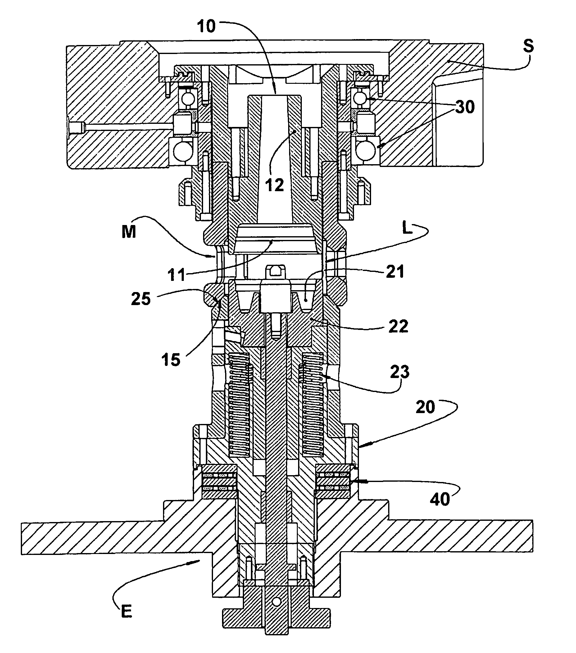
[0025]The figures of the enclosed drawings illustrate the bearing arrangement applied to a centrifugation injection mold of an aluminum cage, which is incorporated into a lamination stack of an electric motor rotor, whose construction is well known in the prior art. However, it should be understood that the present bearing arrangement can be applied to molds for the centrifugation injection of other parts that can be negatively affected by the disalignment between the mold parts during the solidification of the heat injected metal.

[0026]The illustrated mold M comprises an upper mold portion 10, and a lower mold portion 20, which are relatively and axially displaceable between positions of the upper mold 10 defining an upper cavity 11 and incorporating an upper tubular projection 12 for liquid metal supply. In order to be able to rotate around its axis during the centrifugation of the liquid metal in the solidification phase inside the mold M, the upper mold portion 10 is mounted to ...


PUM

PropertyMeasurementUnit
thicknessaaaaaaaaaa
diameteraaaaaaaaaa

Abstract

A bearing arrangement for a centrifugation injection mold, comprising an upper mold portion (10) and a lower mold portion (20), which are respectively and rotatively mounted to an upper bearing (30) and to a lower bearing (40), the latter comprising: a first flat ring (41) affixed to a machine structure (E) and presenting a radial gap that is internal in relation to the lower mold portion (20); an annular cage (42) bearing spheres (44) seated on the first flat ring (41), said annular cage (42) presenting radial gaps that are external and internal in relation to the machine structure (E) and to the lower mold portion (20), respectively; and a second flat ring (45) inferiorly seated on the spheres (44) of the annular cage (42) and maintaining radial gaps that are external and internal in relation to the machine structure (E) and to the lower mold portion (20), respectively, axially bearing the latter. The lower mold portion (20) incorporates an annular conical seat (25) on which is seated, when the mold (M) is taken to the closed position, an annular conical guide (15) incorporated to the upper mold portion (10).

Description

CROSS-REFERENCE TO RELATED APPLICATION[0001]This application is a 371 of PCT / BR02 / 00177 filed on Dec. 9, 2002.FIELD OF THE INVENTION[0002]The present invention refers to a bearing arrangement for two-piece molds used in the centrifugation injection of the cage made of aluminum or other adequate material into the stack of steel laminations of an electric motor rotor, particularly the rotor of small electric motors, such as those used in the hermetic compressors of small refrigeration systems.BACKGROUND OF THE INVENTION[0003]It is already known from the prior art the injection effected by centrifugation of the aluminum cages in rotors, which are formed by a stack of overlapped annular steel laminations provided with openings that are longitudinally aligned with the openings of the other laminations of the stack, in order to define a plurality of axial channels interconnecting the external faces of the end laminations of the stack and which are angularly spaced from each other along a ...

Claims


Application Information

Patent Timeline
Patent Type & Authority Patents(United States)
IPC IPC(8): B22D13/00F16C35/063B22D13/04B22D13/10B22D19/00F16C19/10F16C33/38F16C35/067
CPCB22D13/04B22D13/10F16C33/40F16C19/10F16C19/55B22D19/0054
Inventor RAMIREZ, RIVIO ARTUROSARDO, ANTONIO
Owner EMPRESA BRASILEIRA DE COMPRESSORES SA (EMBRACO)
Why Eureka
Try Eureka