Centrifugation injection mold

a centrifugation injection and mold technology, applied in the direction of rotors, foundation moulding apparatuses, applications, etc., can solve the problems of affecting the quality of the rotor and consequently affecting the efficiency of the electric motor to be formed, and limiting the automation of the operation of loading the lamination stack

Inactive Publication Date: 2008-06-17
EMPRESA BRASILEIRA DE COMPRESSORES SA (EMBRACO)
View PDF3 Cites 0 Cited by
  • Summary
  • Abstract
  • Description
  • Claims
  • Application Information

AI Technical Summary

Benefits of technology

[0014]Aiming at solving the deficiencies of the prior art centrifugation injection molds, in which the upper and lower mold cavities are mounted to a single lower bearing assembly and allowed to rotate therein, the present invention proposes a mold with a relatively simple and efficient construction, which assures the balanced rotation of the mold during the solidification of the cage in the lamination stack, avoiding vibrations and rupture of the component parts of the cage, particularly its bars, without limiting the access to the interior of the mold in the automatic operations of loading the lamination stack in the mold and extracting the centrifuged rotor.SUMMARY OF THE INVENTION
[0017]The constructive arrangement defined above allows for maintaining the two mold portions correctly positioned and aligned in the closed mold position by means of the axial columns, the mold being supported by only one assembly of bearings affixed to the machine structure and which support and allow the rotation of the lower mold portion. The upper mold portion is conducted to be engaged with the lower mold portion in a positioning that is guaranteed by the axial columns, which are rigidly and correctly affixed to the lower mold portion. This assembly eliminates the problem of the unaligned axes of the two mold portions.
[0018]Besides the above-mentioned aspect, the present construction allows the upper mold portion to be completely removed from the axial columns and spaced therefrom by means of a preferably robotized positioning device, whereby the product to receive the injection, for example the rotor of the electric motor, can be easily positioned inside the open mold, seated on the lower mold portion after being axially displaced downwards through the inside of the axial columns, independently of the angular position in which said axial columns are found in the lower mold portion.

Problems solved by technology

A major problem caused by said vibrations of the rotating mold during the solidification of the aluminum is that the bars of the cage, which are formed inside the axial channels of the lamination stack, and even the rings, tend to present cracks, the bars being transversally broken in the interior of the lamination stack in a manner not perceived by external visual observation of the finished rotor.
The rupture or crack of one or more bars or of the upper and lower rings of the cage considerably impairs the quality of the rotor and consequently the efficiency of the electric motor to be formed.
The upper cavity is axially displaced, guided by the columns, to open and close the mold, whereby the upper cavity is retained in a sliding relationship with the columns, considerably limiting the automation of the operations of loading the lamination stack in the mold and extracting the centrifuged rotor, besides causing problems of concentricity and rotor strike.
This characteristic of the solutions in which there is only one lower bearing and the upper cavity is axially displaced along the columns between the open and closed mold positions requires complex solutions to reach a high degree of automation in the production of the rotors with a short cycle time, impairing the productivity.

Method used


Image

  • Centrifugation injection mold
  • Centrifugation injection mold
  • Centrifugation injection mold

Examples


Embodiment Construction

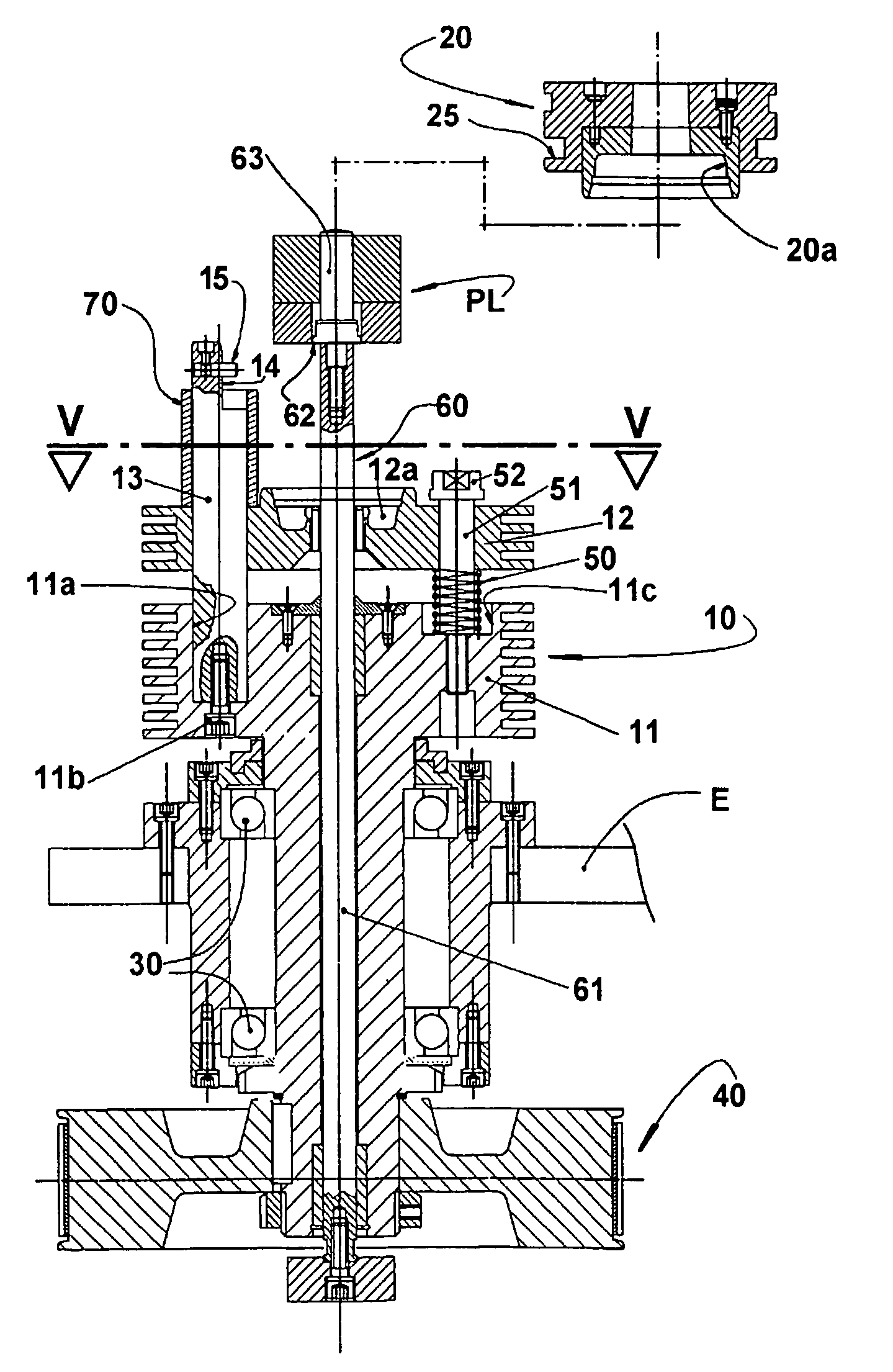
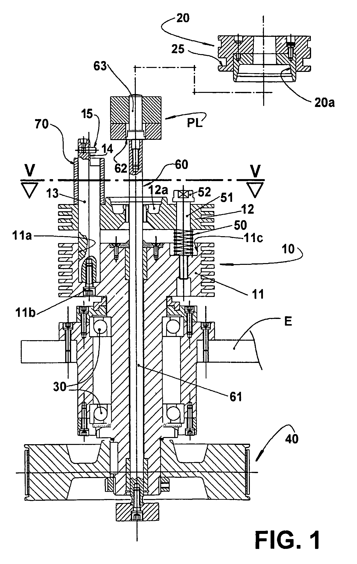
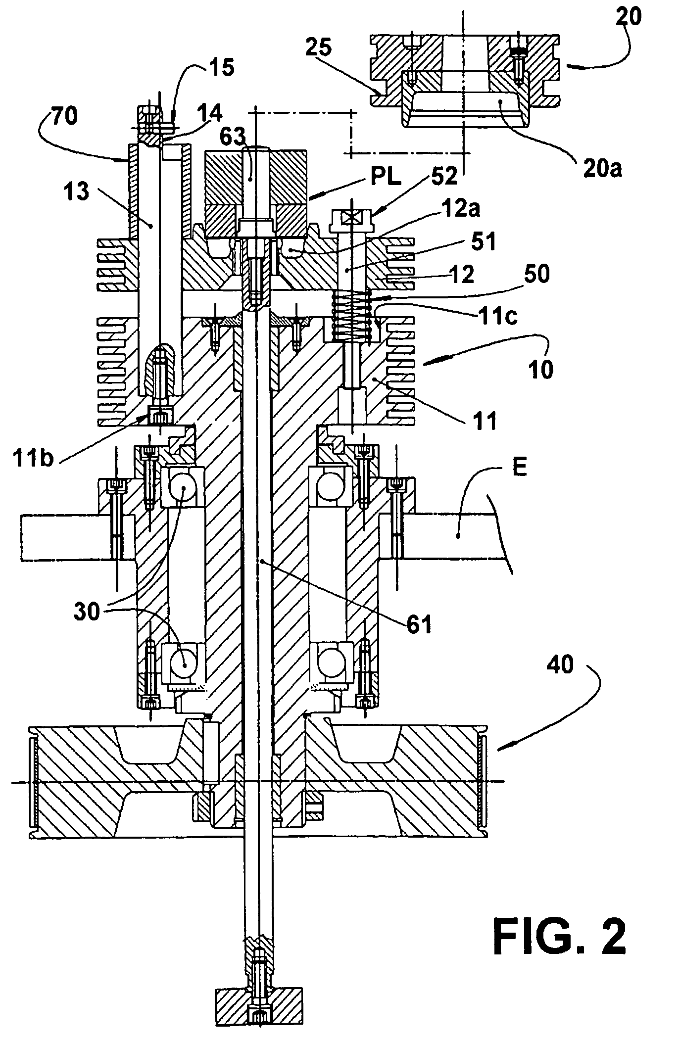
[0025]The figures of the enclosed drawings illustrate the mold used for the injection, by centrifugation, of an aluminum cage incorporated in a lamination stack of an electric motor rotor, this rotor construction being well known in the art. However, it should be understood that the present mold might be applied for the centrifugation injection of other parts that can be negatively affected by the misalignment that occurs between the mold parts during the solidification of the injected hot metal.

[0026]The illustrated mold comprises a lower mold portion 10 and an upper mold portion 20 which are coaxially displaced between open and closed mold positions, as described ahead.

[0027]The lower mold portion 10 presents a basic block 11 downwardly extended to be mounted onto bearing means 30 and allowed to rotate therein. The bearing means 30 are axially spaced from each other and affixed to a machine structure E, generally a machine structure for centrifugation injection. A lower end portio...


PUM

PropertyMeasurementUnit
axial displacementaaaaaaaaaa
gravityaaaaaaaaaa
elasticaaaaaaaaaa

Abstract

A centrifugation injection mold comprising: a lower mold portion having a basic block the lower portion of which is mounted to and rotates within bearing means that are affixed to a machine structure, a plurality of axial columns the bottom portions of which are affixed around the outer portions of the basic block, and a moveable block defining a lower mold cavity and being mounted in a sliding relationship to the axial columns, in order to be axially displaced between an open mold position and a closed mold position; an impelling means operatively associated with the machine structure and with the moveable block for displacing the moveable block to the open mold position against the action of an elastic means; a locking means mounted to each axial column; and an upper mold portion to be removably seated on the axial columns and affixed thereto by the locking means in a closed mold position.

Description

CROSS REFERENCE TO PRIOR APPLICATION[0001]This is a U.S. national phase application under 35 U.S.C. §371 of International Patent Application No. PCT / BR03 / 00064, filed May 15, 2003, and claims benefit of Brazilian Patent Application No. PI 0202033-5, filed May 17, 2002 which is incorporated by reference herein. The International Application was published in English on Nov. 27, 2003 as WO 03 / 097274 A2 under PCT Article 21(2).FIELD OF THE INVENTION[0002]The present invention refers to a two-piece mold used in the injection, by centrifugation, of the cage made of aluminum or other adequate material into the stack of steel laminations of the rotor of an electric motor, particularly the rotor of small electric motors, such as those used in the hermetic compressors of refrigeration systems.BACKGROUND OF THE INVENTION[0003]It is already known from the prior art the centrifugation injection of the aluminum cages in rotors, which are formed by a stack of overlapped annular steel laminations p...

Claims


Application Information

Patent Timeline
Patent Type & Authority Patents(United States)
IPC IPC(8): B22D13/00B22D19/00B22D13/04B22D13/10
CPCB22D13/04B22D13/101B22D19/0054B22D13/10B22D19/00
Inventor RAMIREZ, RIVIO ARTURO
Owner EMPRESA BRASILEIRA DE COMPRESSORES SA (EMBRACO)
Why Eureka
Try Eureka