Conduit insert for optical fiber cable

a technology of optical fiber cable and conduit, which is applied in the direction of cables, power cables, instruments, etc., can solve the problems of difficult to insert a second cable into a conduit which already contains a first cable, many unused or “dead” space within such a conduit, and the inability to insert the second cabl

Inactive Publication Date: 2006-08-01
MILLIKEN & CO
View PDF83 Cites 22 Cited by
  • Summary
  • Abstract
  • Description
  • Claims
  • Application Information

AI Technical Summary

Problems solved by technology

While such conduit provides excellent protection for communication cable, there is also much unused or “dead” space within such a conduit.
However, it has been found that it is difficult to merely insert a second cable into a conduit which already contains a first cable.
When a rope is blown into a conduit already containing a cable, or a second cable is “snaked” through the conduit, they are often impeded by the first cable, making it impossible to insert the second cable.
A problem has been encountered in that when conduit is placed over long distances, undulations will invariably occur therein.
Also, planned curves, such as at underpasses or the like, will often be encountered rendering the placement of known dividers therein difficult, if not impossible.

Method used


Image

  • Conduit insert for optical fiber cable
  • Conduit insert for optical fiber cable
  • Conduit insert for optical fiber cable

Examples


Embodiment Construction

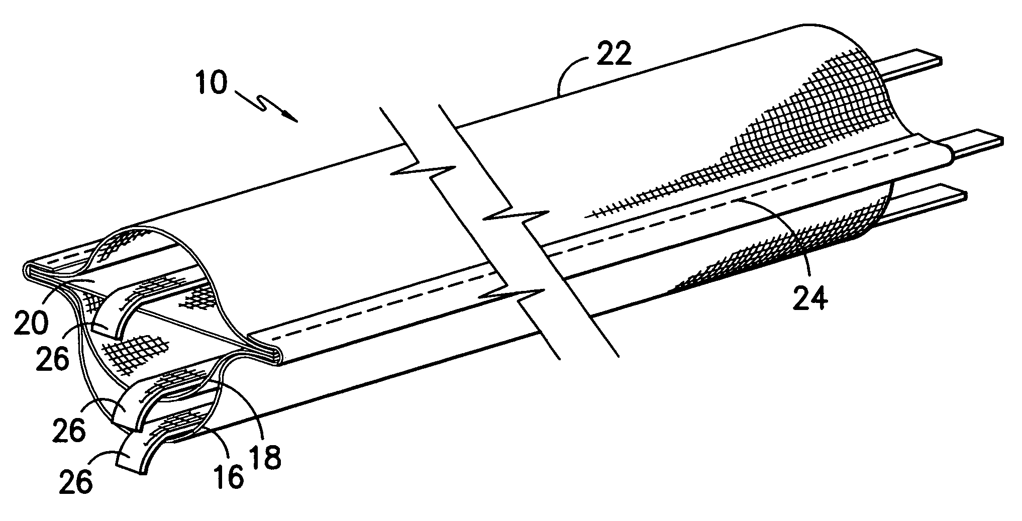
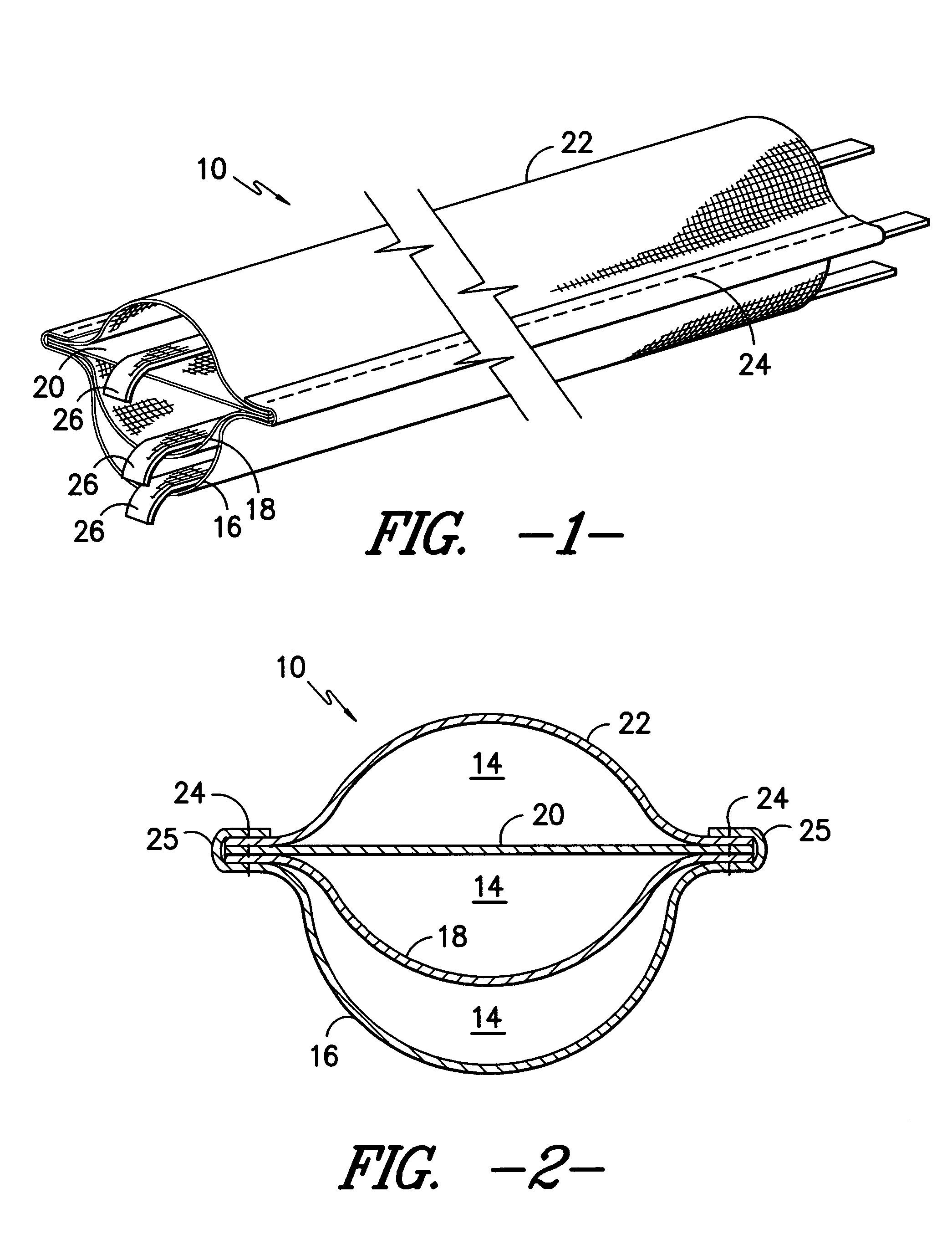
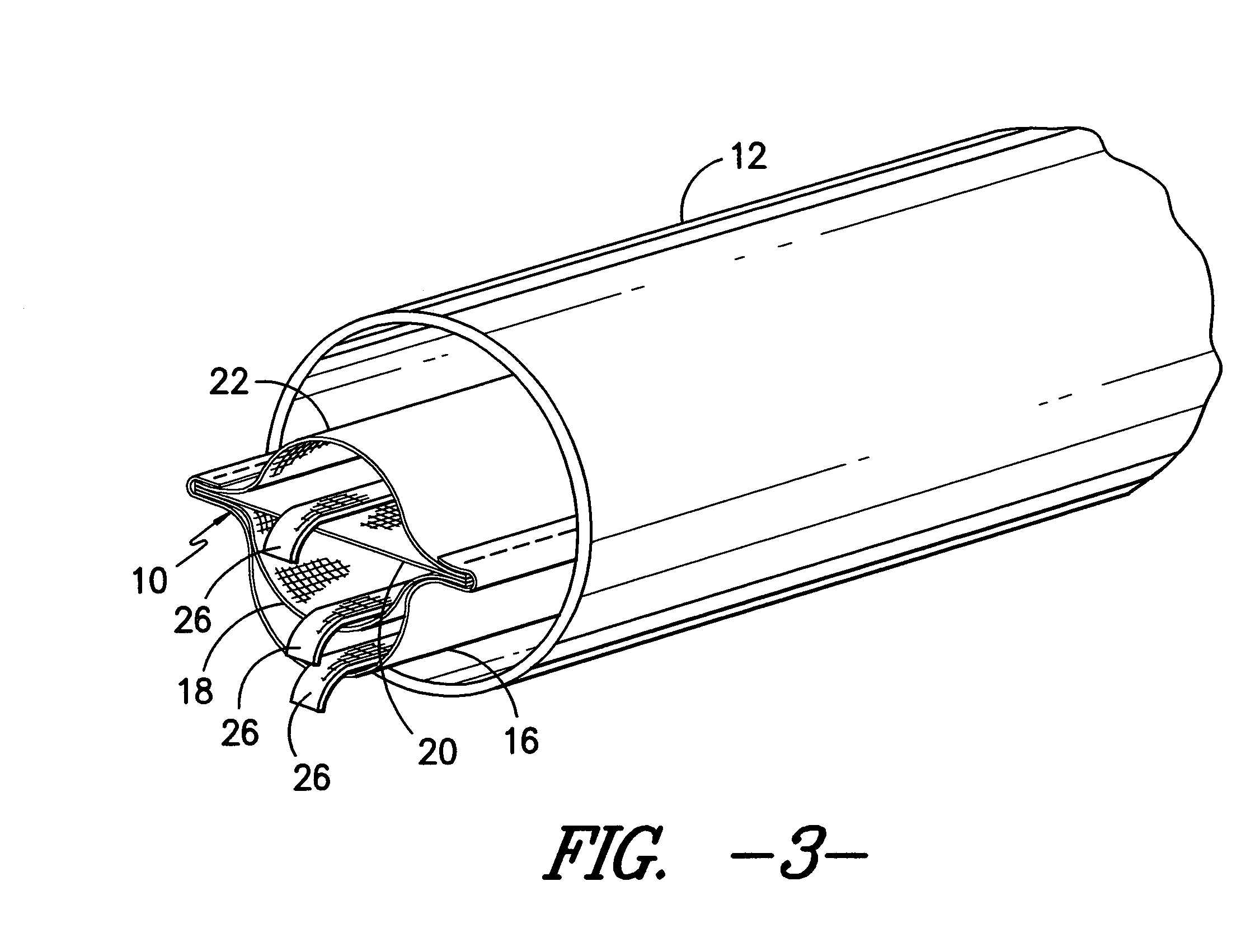
[0020]Referring now to the drawings, the reference number 10 represents an insert, which may be referred to as an innerduct, to be inserted in an optical fiber cable conduit 12. As shown in FIG. 3, a single innerduct 10 is shown in a conduit 12, but it should be understood that multiple innerducts like the innerduct 10 can be inserted in a conduit 12 depending on the diameter of the conduit 12. For example, it is contemplated that three such innerducts can be inserted in a 4″ diameter conduit providing nine channels for the insertion of fiber optic cable.

[0021]Each innerduct 10 defines of a plurality of channels 14 which are formed by interconnected layers of fabric 16, 18, 20 and 22, etc. In the first embodiment of the invention each innerduct 10 has three channels 14 formed by the above noted layers 16, 18, 20 and 22 which are interconnected at their opposite longitudinal side edge portions by having the edge portions 25 of the lower layer 16 overlap the edge portions of the other...


PUM

PropertyMeasurementUnit
elongation percentageaaaaaaaaaa

Abstract

A flexible innerduct structure is configured to contain a cable within a conduit. The innerduct structure includes a pair of adjacent strip-shaped layers of flexible material that are joined along their longitudinal edges to define a channel through which the cable can extend longitudinally through the innerduct structure between the layers. The adjacent layers have differing widths between their longitudinal edges, whereby the wider layer bulges away from the narrower layer to impart an open configuration to the channel. Other features of the innerduct structure relate to the material of which it is formed. Such features includes the structure of the material, such as a woven structure, and further include properties such as melting point, tensile strength, elongation, coefficient of friction, crimp resistance and compression recovery.

Description

RELATED APPLICATIONS[0001]This application is a continuation of copending U.S. patent application Ser. No. 10 / 354,869 filed on Jan. 30, 2003 now U.S. Pat. No. 6,671,440, which is a continuation of U.S. patent application Ser. No. 10 / 138,740, filed May 2, 2002 now abandoned, which is a continuation of U.S. patent application Ser. No. 09 / 928,054, filed Aug. 10, 2001, now issued U.S. Pat. No. 6,421,485, which is a continuation of U.S. patent application Ser. No. 09 / 400,778, filed Sep. 22, 1999, now issued U.S. Pat. No. 6,304,698.BACKGROUND OF THE INVENTION[0002]The present invention generally relates to tubular conduit of the type that might be employed for the housing of underground cables, such as fiber optic cable, coaxial cable, or the like. More particularly, the present invention relates to a partitioning device, which may be inserted into such a conduit such that the conduit is divided into separate areas. Specifically, the present invention is directed toward an elongated parti...

Claims


Application Information

Patent Timeline
Patent Type & Authority Patents(United States)
IPC IPC(8): G02B6/44G02B6/50G02B6/46H01B9/00H01B11/22H02G9/06
CPCG02B6/4459G02B6/508H02G9/065H02G9/06H02G3/0481D03D1/0043G02B6/44
Inventor MORRIS, DAVID DREW
Owner MILLIKEN & CO
Why Eureka
Try Eureka