Electronic lock box with single linear actuator operating two different latching mechanisms

a technology of latching mechanism and electronic lock box, which is applied in the field of electronic lock box, can solve the problem of only valid numeric codes, and achieve the effect of preventing damage to electromechanical components and prolonging the life of cards

Active Publication Date: 2006-08-08
SENTRILOCK
View PDF102 Cites 67 Cited by
  • Summary
  • Abstract
  • Description
  • Claims
  • Application Information

AI Technical Summary

Benefits of technology

[0011]Accordingly, it is an advantage of the present invention to provide an electronic lock box system used in real estate sales systems in which the user carries only a credit card-sized portable memory card, and in which the user receives a diversified numeric value from a central “earinghouse computer,” or from a regional “office computer,” in which the diversified value represents a combination of the epoch time and the user's personal identification number (PIN), when run through an encryption routine. The diversified numeric value periodically changes over time using an algorithm known both to the lock box and to the earinghouse computer, in which system “epoch time” is divided into time intervals (“window intervals” or “window interval periods”) that, when advanced to the next window interval, change the result obtained by decrypting the diversified numeric value. The diversified numeric data resident on the portable memory card is directly transferred to the lock box computer, and this diversified numeric data is then decrypted by the lock box's computer. To allow access to the key compartment (or to unlock the shackle in some circumstances), the user must manually enter the correct ID information on a keypad of the lock box, which in many cases is the user's PIN.
[0012]It is another advantage of the present invention to provide an electronic lock box system used in real estate sales systems which operates in a “contractor mode” having a somewhat lesser security state, so that a contractor is provided with a numeric ID code that can be entered on a keypad of an electronic lock box to obtain access to a secure compartment within the lock box, without the need for a memory card. However, the numeric code is only valid for a predetermined time interval. The “owner” of the lock box provides instructions to the lock box to enable this contractor mode. A central earinghouse computer can be used to generate more than one such contractor mode code for the same time interval (e.g., one day), and the lock box owner uses that information to set up the corresponding lock box, and to inform the one or more contractors as to their correct numeric ID codes to be used during the appropriate time interval.
[0013]It is yet another advantage of the present invention to provide an electronic lock box apparatus that in udes a mechanical attachment device (e.g., a shackle) and a secure compartment with a controlled access member (e.g., a key compartment with a hinged door), in which a single linear actuator is movable in two different directions to either release the shackle or to open the key compartment door.
[0014]It is still another advantage of the present invention to provide an electronic lock box apparatus that in udes a mechanical attachment device (e.g., a shackle) and a secure compartment with a controlled access member (e.g., a key compartment with a hinged door), in which there are latching members that either (1) hold the shackle or key compartment door in place, or (2) release those components from being held in place. A single linear actuator moves to operate these respective latching members, such that movement of the actuator in opposite directions releases either one or the other of these latching members. Once released, the shackle or the key compartment door can later be moved back into their respective “latched” positions and, without further movement by the linear actuator, will become locked in their “held” positions.
[0015]It is a further advantage of the present invention to provide an electronic lock box apparatus that in udes a way of preventing damage to the electromechanical components when a movable part becomes jammed or frozen, without the use of extra overcurrent protection devices that perform no other function.
[0016]It is a yet further advantage of the present invention to provide an electronic lock box apparatus that is designed so that it is impossible for its card expiring access codes to be altered in order to extend the card's life, and thus prevents “immortal keys” from existing. Each memory card / smart card used with the invention's lock box design must be periodically renewed with an encoded value that does not have a predictable pattern from one time window to the next. Therefore, access rights for every card will expire after predetermined time window has passed.

Problems solved by technology

However, the numeric code is only valid for a predetermined time interval.

Method used


Image

  • Electronic lock box with single linear actuator operating two different latching mechanisms
  • Electronic lock box with single linear actuator operating two different latching mechanisms
  • Electronic lock box with single linear actuator operating two different latching mechanisms

Examples


Embodiment Construction

[0053]Reference will now be made in detail to the present preferred embodiment of the invention, an example of which is illustrated in the accompanying drawings, wherein like numerals indicate the same elements throughout the views.

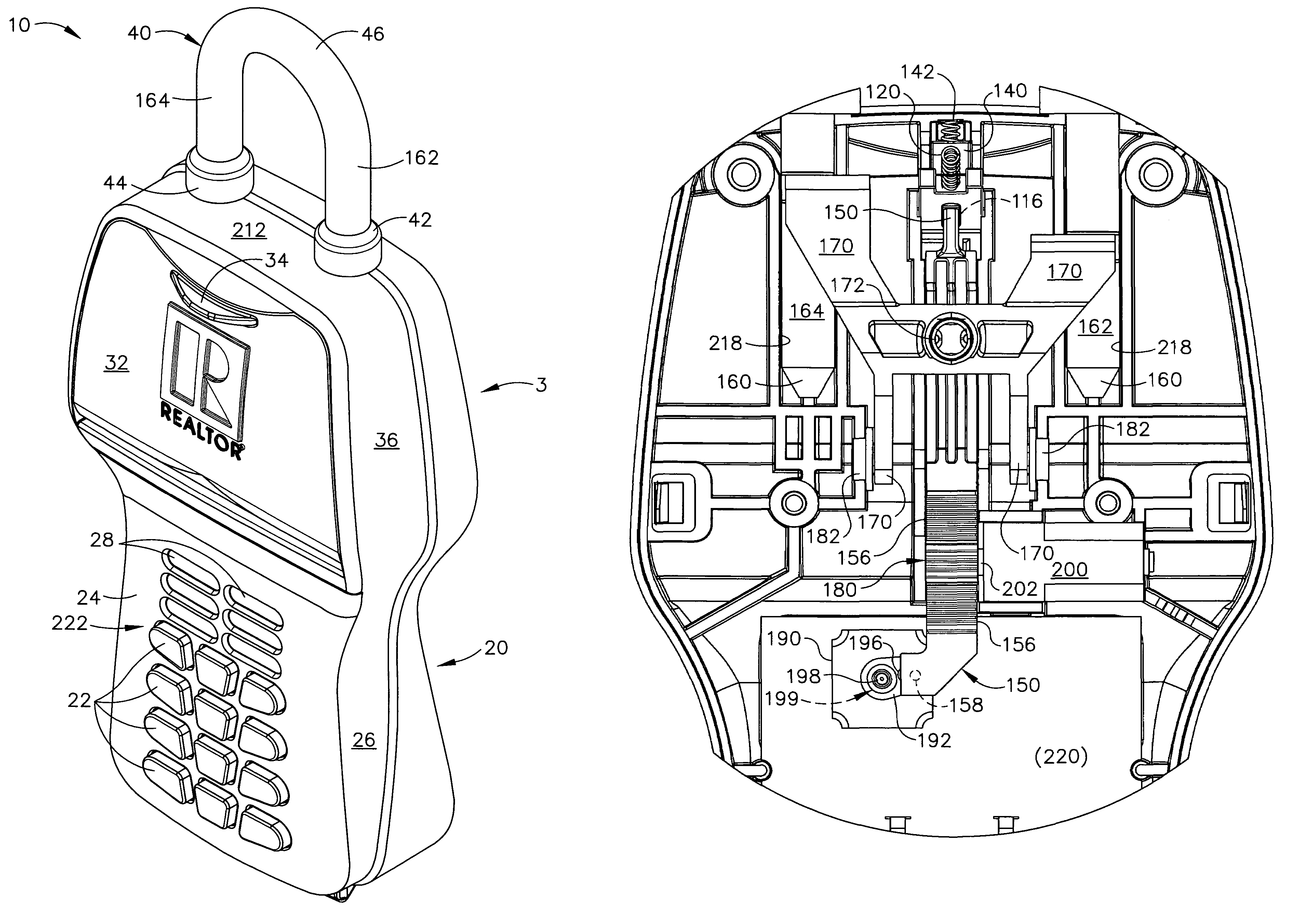
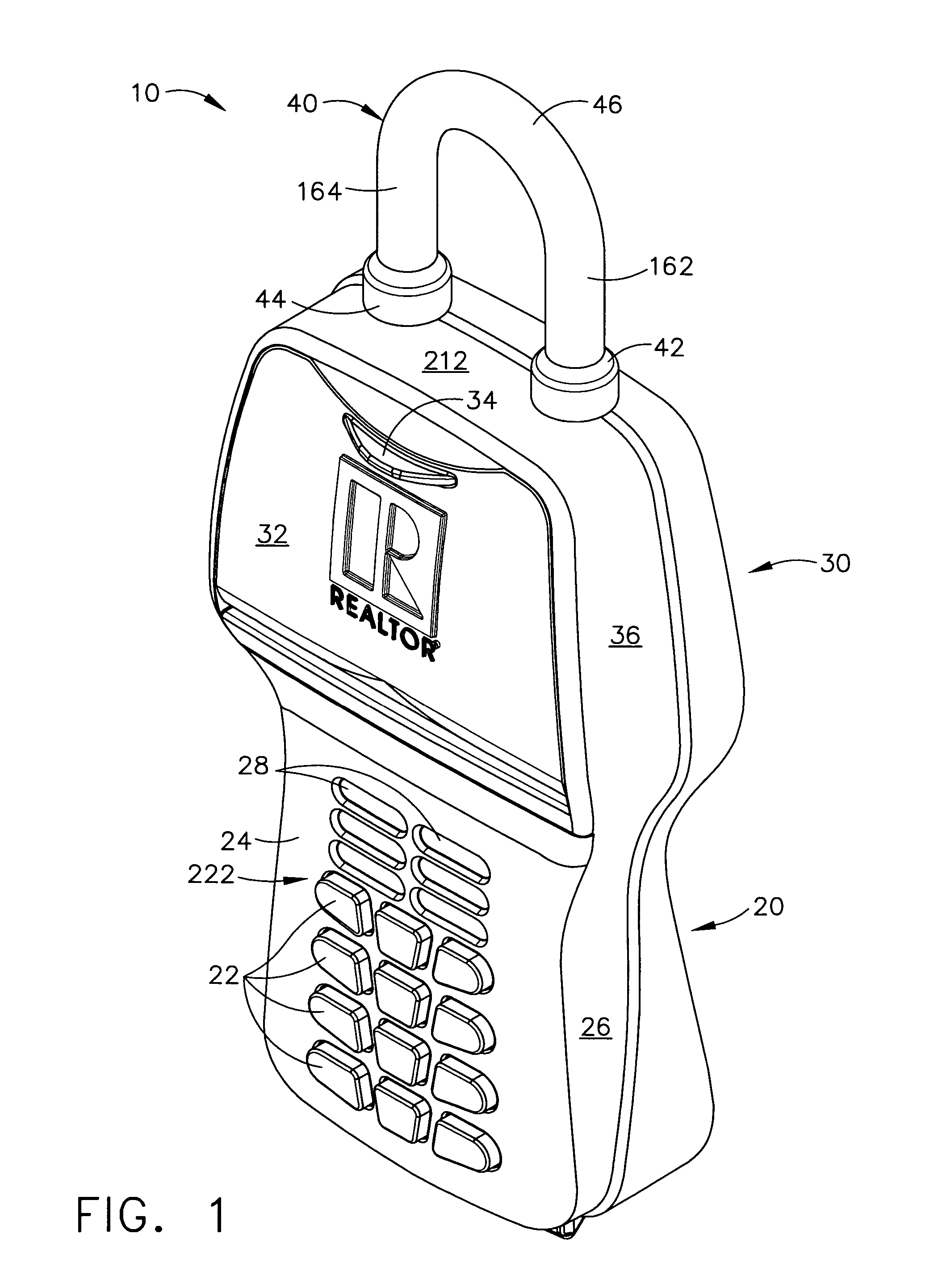
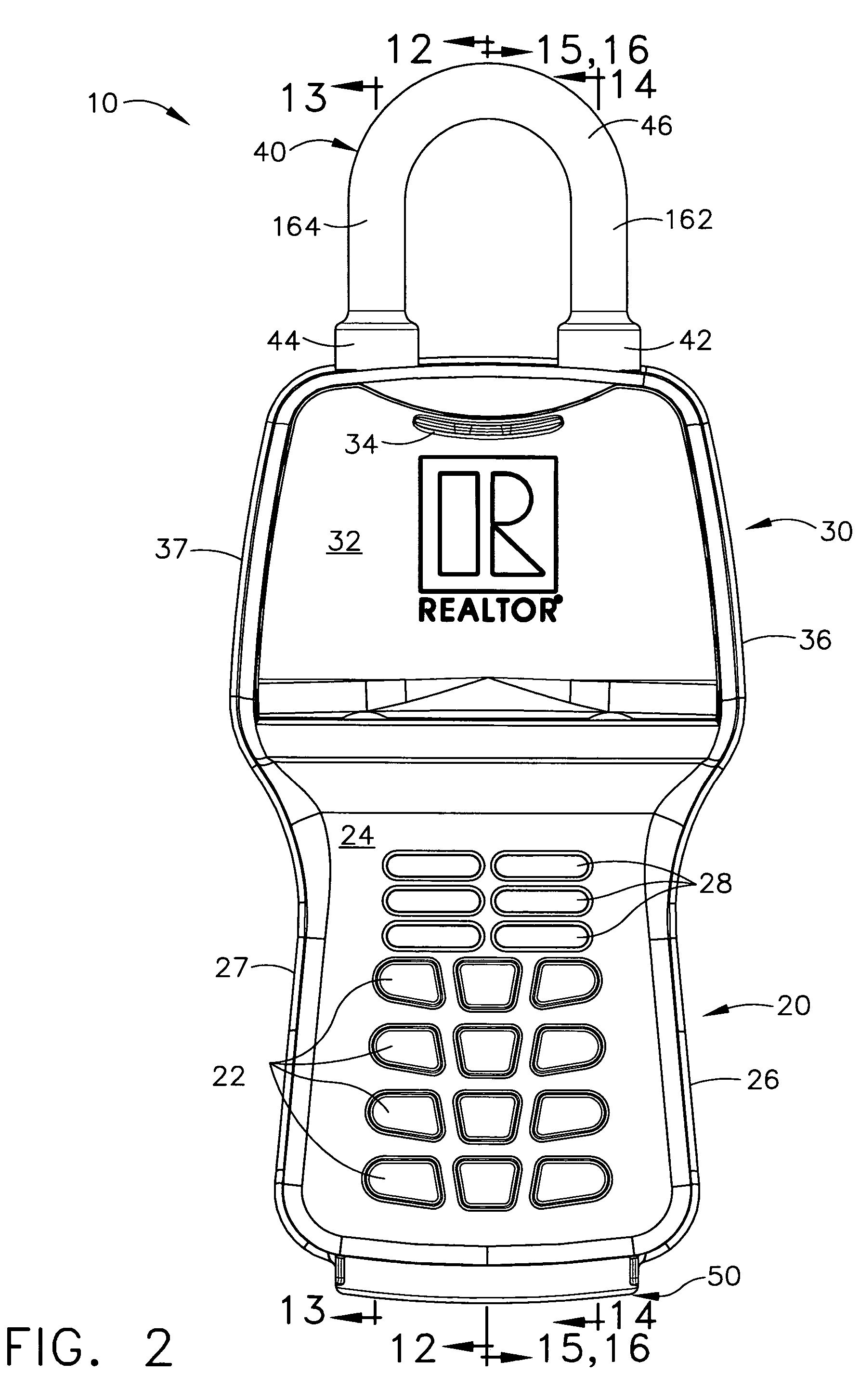
[0054]Referring now to the drawings, FIG. 1 illustrates an electronic lock box generally designated by the reference numeral 10, as constructed according to the principles of the present invention. Lock box 10 has an outer housing, in luding a lower housing portion 20, and an upper housing portion 30, in which the lower housing includes a keypad 222 at a keypad area 24, and the upper housing includes a moveable key compartment door 32. In the keypad area 24, there are multiple individual pushbutton keys 22, and also on the front surface of the keypad area 24, there is a set of indicator lamps 28 that act as an annunciator.

[0055]FIGS. 1–7 illustrate the outer portions of lock box 10 in various views, in which the key compartment door 32 is closed. FIG. 8 i...


PUM


Abstract

An electronic lock box contains a secure compartment for storing keys to a structure. A linear actuator moves in one direction opening the door to the secure compartment, and moves in the opposite direction releasing a shackle that holds the lock box to the structure. A lock box system uses an encryption algorithm to diversify user PIN data at a central computer, and stores that diversified information on a memory card for later use when the user attempts to access a lock box. The central computer and electronic lock box both keep track of system “epoch time,” and the memory card must be presented to the electronic lock box within a correct epoch time window for the diversified PIN data to be successfully decrypted and compared to the user's PIN data that is entered on a keypad of the electronic lock box.

Description

TECHNICAL FIELD[0001]The present invention relates generally to electronic lock equipment and is particularly directed to an electronic lock box of the type that contains a secure compartment for storing keys that allow entry to a structure. The invention is specifically dis osed as an electronic lock box that in udes an internal linear actuator that moves in one direction to open the door to a secure compartment containing a key to the structure, and moves in the opposite direction to release a shackle that holds the lock box to the structure, such as a door handle.[0002]The invention is also directed to an electronic lock box system that uses an encryption algorithm to diversify user PIN data at a central computer, and store that diversified information on a memory card for later use when the user attempts to access a particular lock box. The central computer and the electronic lock box both have time counters that keep track of system “epoch time,” and the memory card must be pre...

Claims


Application Information

Patent Timeline
Patent Type & Authority Patents(United States)
IPC IPC(8): E05B49/00B60L3/00E05B19/00E05B47/00E05B67/00G07C9/00H01H47/00
CPCE05B19/0005G07C9/0069E05B47/0012E05B67/00Y10S70/63E05B2047/002G07C9/00896E05B2047/0016Y10T70/422Y10T70/5031Y10T70/7068Y10T70/7102
Inventor FISHER, SCOTT RNOACK, WILLIAM GEORGESMITH, BRET WILLIAMSTEWART, RANDOLPH C.
Owner SENTRILOCK
Why Eureka
Try Eureka