Quick-acting tool bit holder

a tool bit and quick-acting technology, which is applied in the field of quick-acting tool bit holders, can solve the problems of inordinately expensive and difficult manufacturing of chuck assemblies or bit holders of this type, and achieve the effects of preventing over-retraction and consequent jamming of the retraction collar, facilitating the ease and speed of insertion or removal of the tool bit, and reducing the off-axis “cocking” of the coil spring

Inactive Publication Date: 2006-08-08
BLACK & DECKER INC
View PDF21 Cites 76 Cited by
  • Summary
  • Abstract
  • Description
  • Claims
  • Application Information

AI Technical Summary

Benefits of technology

[0008]In preferred forms of the present invention, the U-shaped spring clip is directly engaged and biased by the coil spring, and both of its legs are curved inwardly around a portion of the chuck's body so that the clip is self-retaining. In this configuration both the curved legs extend around the body to locations on an opposite side of the body's axis from the clip's base in the angular slot. In this way, the direct contact of the clip with the coil spring is directed axially generally through the center of the coil spring so as to keep the coil spring coaxially aligned with the body and thus to minimize off-axis “cocking” of the coil spring.
[0009]Also, in a preferred form of the invention, the corners of the U-shaped clip (at the intersections of the curved legs with the straight base) serve as “stops” for the retraction collar sleeve, by engaging its internal hollow bore as the clip is retracted up the angular slot, in order to prevent over-retraction and consequent jamming of the retraction collar.
[0010]In addition, the preferred coil spring can be provided with at least one of its bights, at either the forward or rearward ends, or at both ends, being axially collapsed in order to form one or more “dead coils” at the coil spring end (or ends). This feature allows the coil spring to more flatly abut the spring clip at the forward end of the coil spring, and / or more flatly engage the stepped portion of the body at the rearward end of the coil spring, thus keeping the coil spring and the retraction collar properly coaxially aligned with the body.
[0011]Finally, in order to facilitate the ease and speed of insertion or removal of the tool bit, and to greater facilitate the chuck's ergonomics, the retraction collar is preferably formed with one or more discontinuities on its radially outer periphery, preferably in the form of circumferentially-extending ribs, to which a polymeric cover is attached and engagingly retained on the periphery of the retraction collar.
[0012]Preferably, a polymeric cover is press-fit over parallel annular ribs formed on the exterior surface of the retraction collar. Ideally, the polymeric cover is formed in a two-shot process, in which an outer layer of thermoplastic elastomer is molded over a copolymer thermoplastic base layer of a contrasting color, such that suitable raised icons, identifiers, logos, or trademarks protrude through the outer layer and are flush with the outer surface of the cover. In the preferred embodiment, the outer layer is black, and the protruding raised portions of the base layer spell out the trademark DeWALT® in yellow letters. As a result, the operator experiences a “soft-grip” tactile sensation that provides an exceptional grip on the chuck assembly, and which further provides a durable, eye-catching display of the manufacturer's livery and identifiers.

Problems solved by technology

Although this basic design has performed well, chuck assemblies or bit holders of this type have been found to be inordinately expensive and difficult to manufacture due to the relatively large number of parts required, as well as frequently requiring the operator to actuate a sleeve, collar or other component part during both the insertion and the removal of the tool bit.

Method used


Image

  • Quick-acting tool bit holder
  • Quick-acting tool bit holder
  • Quick-acting tool bit holder

Examples


Embodiment Construction

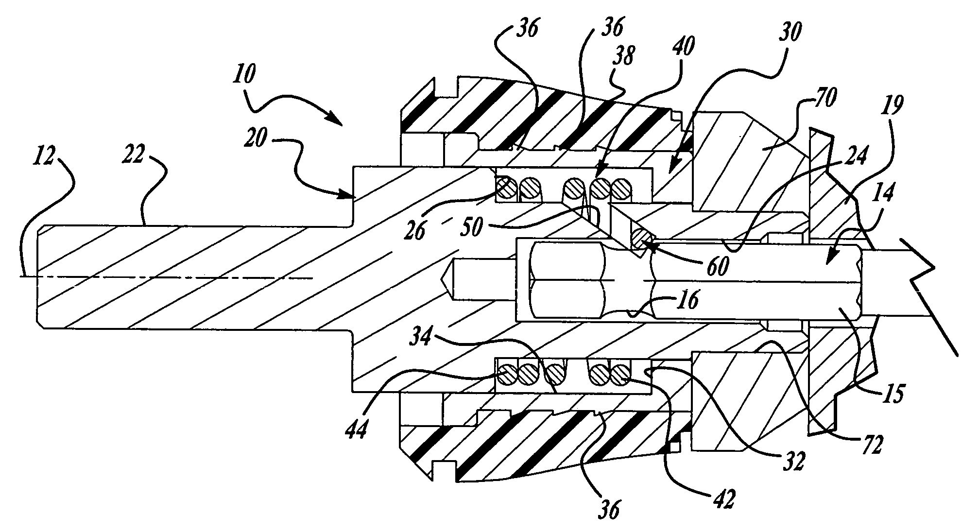
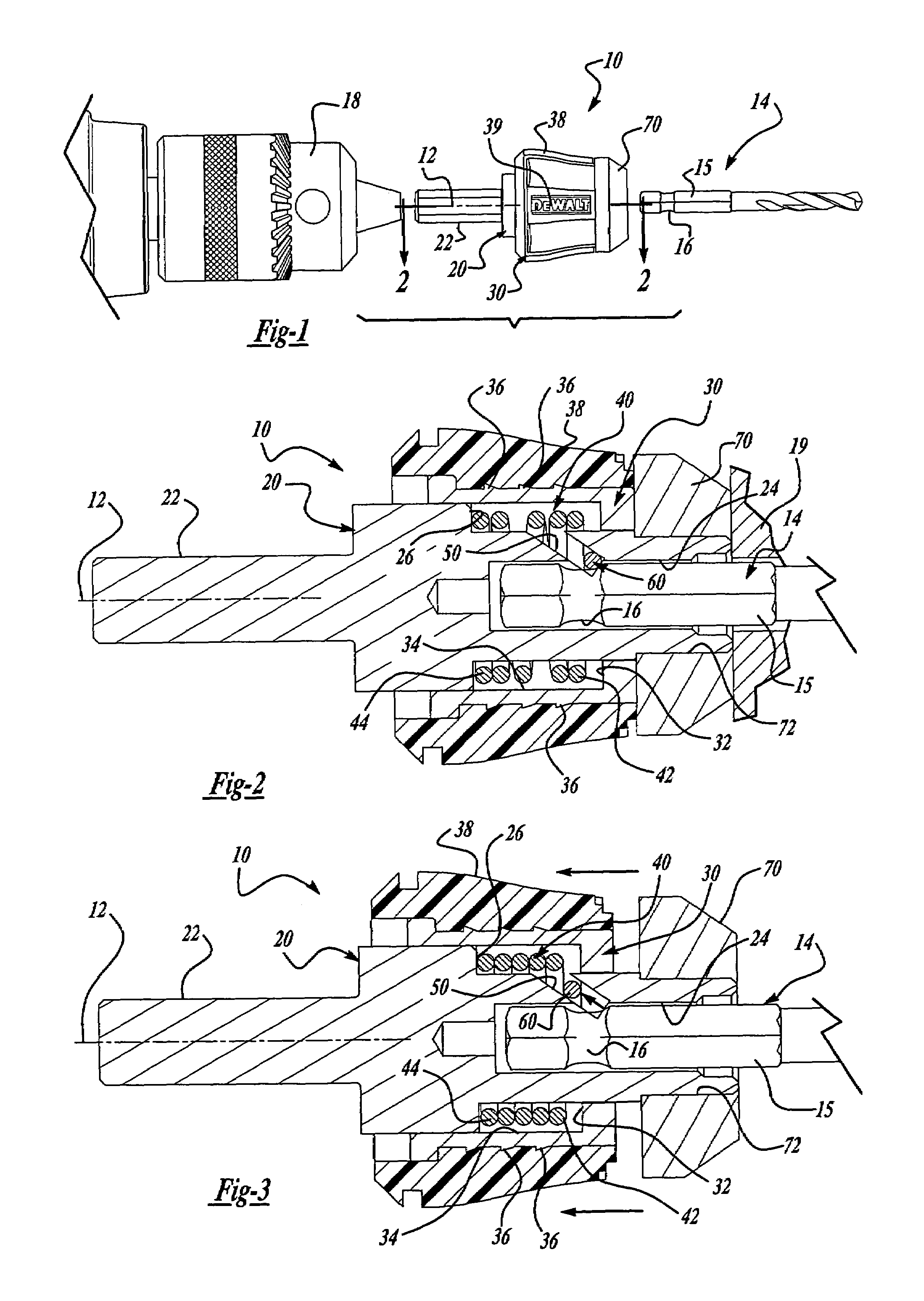
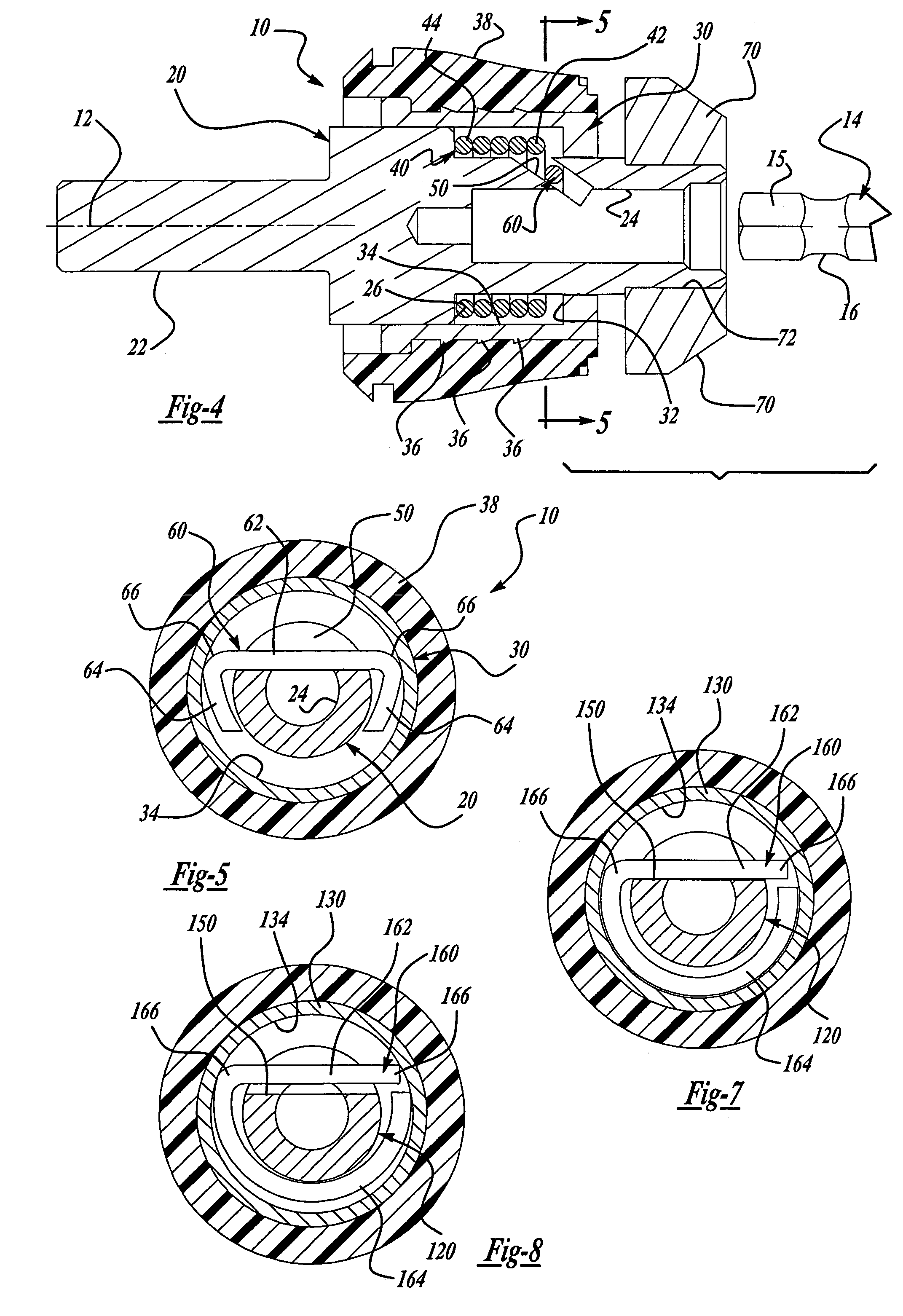
[0027]FIGS. 1 through 6 depict one exemplary preferred embodiment, and FIGS. 7–8 and FIGS. 9–11 depict alternate embodiments, of a chuck assembly or tool bit holder according to the present invention, shown merely for purposes of illustration. One skilled in the art will readily recognize, from the following discussion and the accompanying drawings, that chuck assemblies or bit holders of configurations other than that of this exemplary illustration can also advantageously employ the principles of the present invention.

[0028]In FIGS. 1 through 6, an exemplary chuck assembly or bit holder 10 is attachable to a power tool or to a hand tool 18 to be driven for rotation about an axis 12. The chuck assembly 10 is adapted to removably receive a tool bit 14 having a generally hex-shaped shank 15 with a circumferential recess 16 formed therein. The tool bit 14 can be any of a number of well-known bits, including drill bits, nut driver bits, screwdriver bits, or other types of fastener drive...


PUM

PropertyMeasurementUnit
speedaaaaaaaaaa
coloraaaaaaaaaa
diameteraaaaaaaaaa

Abstract

A “snap-in” bit chuck assembly for a rotary hand or powered tool, includes an elongated body having a hex shank at its rearward end, an elongated retraction collar slidably disposed on the body, and an outer retaining collar fixed to the forward end of the body. The body has a coaxial hex socket formed therein to allow a reversible tool to be inserted thereinto. A slot is formed in the body, between the outer surface of the body and the internal hex socket. A coil spring surrounds the body, inside the retraction collar, and normally biases the retraction collar forwardly and biases a retaining clip toward the bottom of the angular slot. The retaining clip slides outwardly in the angular slot, against the bias of the coil spring, as the reversible tool is inserted, where a recess on the reversible tool is engaged and retained by the clip. The tool is removed by sliding the retraction collar rearwardly, to compress the coil spring and allow the retaining clip to retract back up the slot. The clip is directly engaged by the coil spring and has two legs extending about the body so that the clip is self-retaining. The clip legs extend around the body such that the retraction force on the coil spring is directed through the center of the coil spring to keep it coaxially aligned with the body.

Description

CROSS-REFERENCE TO RELATED APPLICATION[0001]This application is a continuation-in-part application of U.S. application Ser. No. 09 / 105,661 filed Jun. 26, 1998 now U.S. Pat. No. 6,053,675 entitled QUICK-ACTING TOOL BIT HOLDER, the specification and drawings are herein expressly incorporated by reference.BACKGROUND AND SUMMARY OF THE INVENTION[0002]The invention relates generally to power or hand tool bit holders, variously known as “auxiliary chucks”, “chucks”, or “adapters”, for removably receiving tool bits, such as fastener drivers, drill bits, or the like, for rotation therewith when the power tool is actuated or the hand tool is manually rotated. More particularly, the present invention relates to chuck assemblies or adapters configured for rapid and easy insertion and removal of a tool bit.[0003]Auxiliary chucks for power and hand tools have become increasingly common, especially as the need and desirability of wider versatility in the use of power tools and hand tools has incr...

Claims


Application Information

Patent Timeline
Patent Type & Authority Patents(United States)
IPC IPC(8): B23B31/107B25F5/02B29C45/16
CPCB23B31/1074B25B15/001B25B23/0035B23B2226/33B23B2260/136Y10T279/17811Y10T408/95Y10T29/49826Y10T279/3418B23B31/1072B23B31/1079
Inventor BOYLE, DAVID C.MCKENZIE, TIMOTHY T.
Owner BLACK & DECKER INC
Why Eureka
Try Eureka