Reflective heat patch

a heat patch and reflective technology, applied in the field of heat patches, can solve the problems of insufficient heat that may be safely applied by heat patches, insufficient infrared energy typically used to provide optimal therapy, and limited heat patch temperature, and achieve the effect of superior therapy

Inactive Publication Date: 2006-08-08
KIMBERLY-CLARK WORLDWIDE INC
View PDF17 Cites 24 Cited by
  • Summary
  • Abstract
  • Description
  • Claims
  • Application Information

AI Technical Summary

Benefits of technology

[0007]In one aspect, the present invention relates to a heat patch for providing therapy to a body. The heat patch includes a reflective layer and a heat source that is attached to the reflective layer. The reflective layer reflects infrared energy emitted by the body back into the body while the heat source applies heat to the body. The combination of supplying heat and reflecting infrared energy potentially provides superior therapy to people with relatively deep tissue injuries.
[0008]In another aspect, the present invention relates to a heat patch for providing therapy to a body where the heat patch includes an enclosure made from a gas-permeable layer and a reflective layer that is attached to the gas-permeable layer. A heating composition is sealed inside the enclosure. The heating composition generates heat when a gas (e.g., air) is received through the gas-permeable layer. The reflective layer reflects infrared energy emitted by the body back into the body. The heat generated by the heating composition is easily controlled such that heat patch can be maintained at a temperature that is well above ambient temperature.

Problems solved by technology

The temperature of the heat patch must be limited because applying too much heat to the body causes discomfort or burning.
The level of heat that may be safely applied by heat patches is typically insufficient to provide adequate therapy to deeper muscles or joints within the body.
One concern with using reflectors is that they typically do not reflect enough infrared energy to provide optimal therapy, especially when the ambient temperature near the body is low.

Method used


Image

  • Reflective heat patch
  • Reflective heat patch
  • Reflective heat patch

Examples


Embodiment Construction

[0017]In the following detailed description, reference is made to the accompanying drawings, which show specific embodiments in which the invention may be practiced. These embodiments are described in sufficient detail to enable those skilled in the art to practice the invention. It is to be understood that other embodiments may be utilized and structural changes made, such that the following detailed description is not to be taken in a limiting sense.

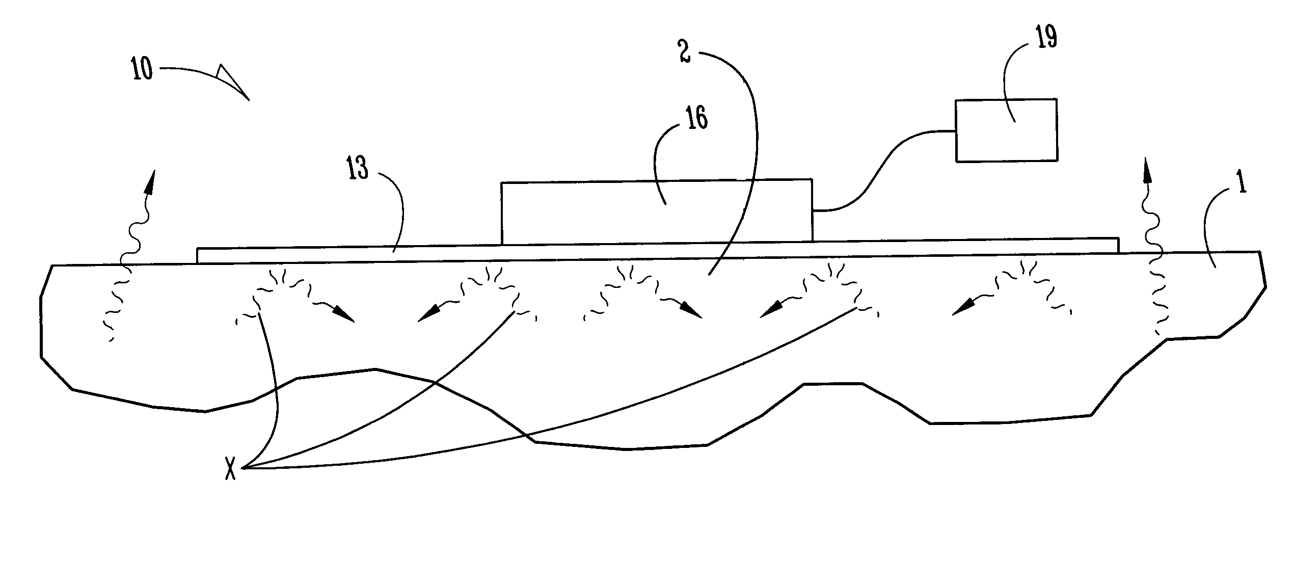
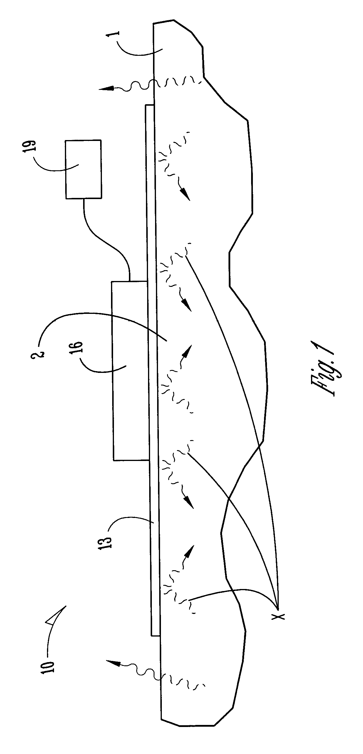
[0018]FIG. 1 illustrates a heat patch 10 for providing therapy to a portion 2 of a body 1. The heat patch 10 includes a reflective layer 13 and a heat source 16 that is attached to the reflective layer 13. The reflective layer 13 reflects infrared energy X emitted by the body 1 back into the portion 2 of the body 1, and the heat source 16 applies heat to the body 1.

[0019]The combination of generated heat and reflected infrared energy provides effective therapy to the portion 2 of the body 1. The heat applied by the heat patch 10 not on...


PUM


Abstract

A heat patch and method for providing therapy to a body. The heat patch includes a reflective layer and a heat source that is attached to the reflective layer. The reflective layer reflects infrared energy emitted by the body back into the body while the heat source applies heat to the body. The combination of supplying heat and reflecting infrared energy provides effective therapy to people with relatively deep tissue injuries. In another aspect, the heat patch includes an enclosure made from a gas-permeable layer and a reflective layer attached to the gas-permeable layer. A heating composition is sealed inside the enclosure to generate heat when a gas (e.g., air) is received through the gas-permeable layer. The heat generated by the heating composition is easily controlled such that heat patch can be maintained at a temperature well above ambient temperature.

Description

FIELD[0001]The present invention relates to a heat patch and more particularly to a heat patch that transfers heat to a body and reflects infrared energy into the body when the heat patch is placed on or near the body.BACKGROUND[0002]A variety of heat-treating methods are used to treat symptoms such as stiffness, muscle pain, cold hands and feet, lumbago, rheumatism and neuralgia (among others). Some known heat-treating methods include direct application of heat to the body using items such as a towel, jelly and / or paste. One concern with such heat-treating methods relates to their ability to apply heat for extended periods of time.[0003]Another heat-treating method utilizes a heat patch to apply heat to an injured portion of a body. Many heat patches generate heat internally, such as via an exothermic chemical reaction, to raise the temperature of the heat patch. The temperature of the heat patch must be limited because applying too much heat to the body causes discomfort or burnin...

Claims


Application Information

Patent Timeline
Patent Type & Authority Patents(United States)
IPC IPC(8): A61F7/00A61F7/02A61F7/03A61F7/08
CPCA61F7/034A61F7/007A61F2007/036A61F2007/0255
Inventor PURCELL, RICKY W.
Owner KIMBERLY-CLARK WORLDWIDE INC
Why Eureka
Try Eureka