Self locking fixable intervertebral implant

a self-locking, intervertebral implant technology, applied in the field of intervertebral implants, can solve the problems of forming loops and tying knots, affecting the fitting effect, and reducing the time consumption of tying knots, so as to facilitate fitting

Inactive Publication Date: 2006-08-08
ZIMMER SPINE INC
View PDF10 Cites 392 Cited by
  • Summary
  • Abstract
  • Description
  • Claims
  • Application Information

AI Technical Summary

Benefits of technology

[0015]In this way, when said tie is moved in translation to clamp the spinous process in said groove, the self-locking fixing member is entrained in translation in a direction parallel to said second direction and said studs bear against the edge of the oblong openings to immobilize said member. Said oblong openings advantageously have an elastically deformable cons

Problems solved by technology

Although installing the block between the two spinous processes is relatively quick and easy, attaching the ties to the block is much more difficult, because of the lack o

Method used


Image

  • Self locking fixable intervertebral implant
  • Self locking fixable intervertebral implant
  • Self locking fixable intervertebral implant

Examples


Embodiment Construction

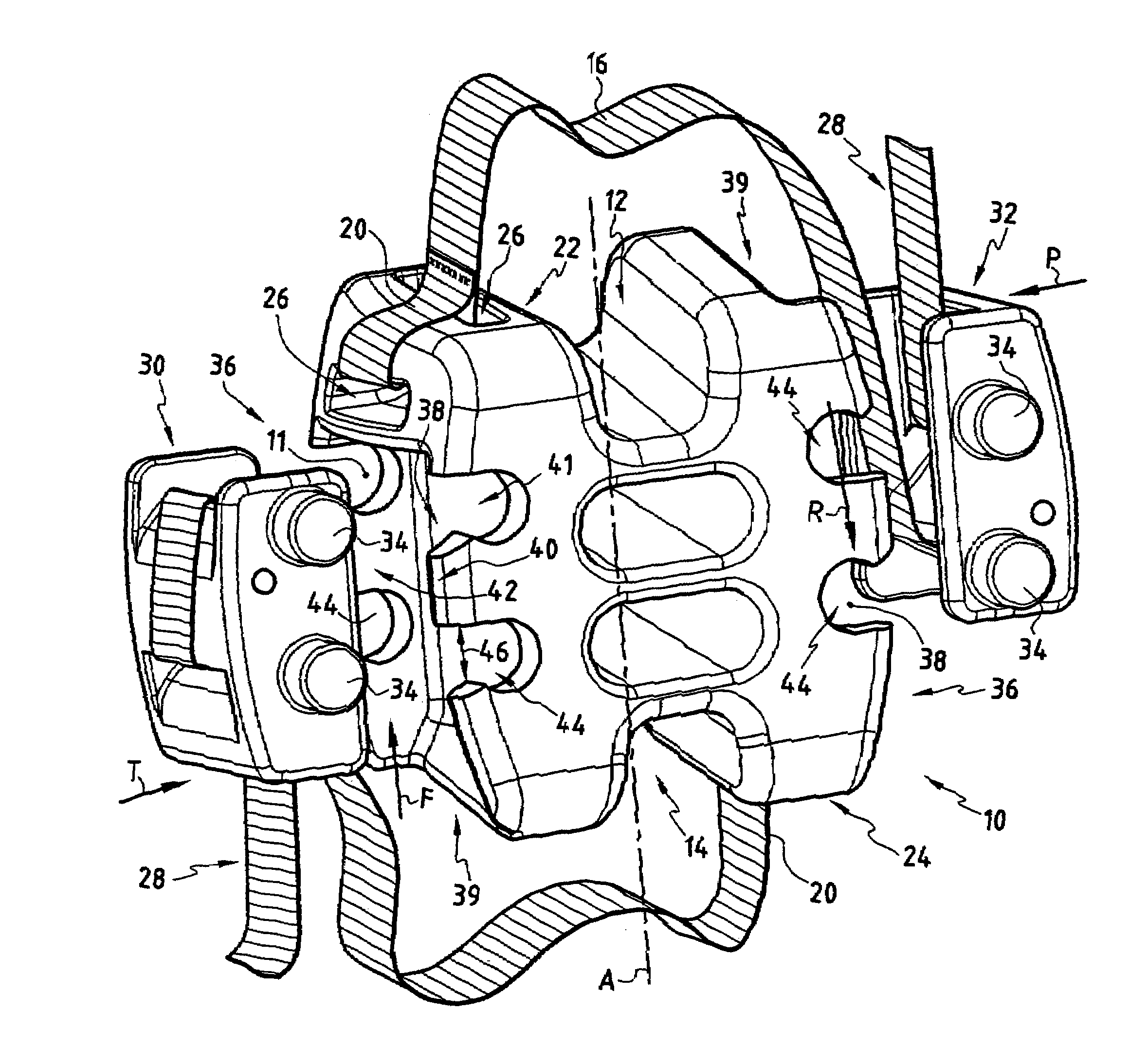
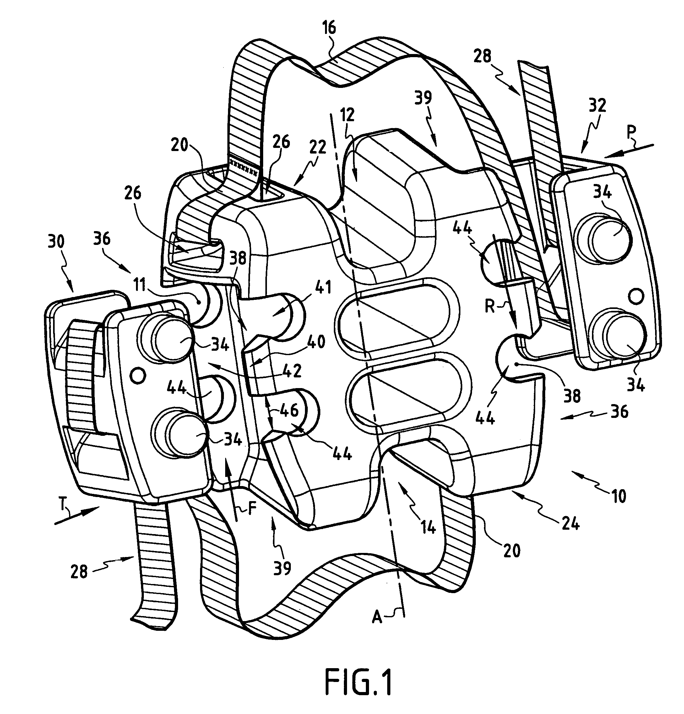
[0021]FIG. 1 shows an intervertebral implant including a block 10 having a longitudinal axis A on which there are a top groove 12 and a bottom groove 14, the two grooves 12 and 14 being on opposite sides of the block. Each of the grooves 12 and 14 is adapted to receive a spinous process and the block is mounted between the spinous processes of two vertebrae to limit their movement towards each other.

[0022]The implant further includes two ties 16 and 18 in the form of tapes, and the first ends of these ties are connected to respective diagonally opposite flanges 22 and 24. The connection between the first end 20 of a tie and the respective flange 22, 24 is obtained by means of a bore 26 passing through the end of the flange 22, 24 and by sewing the first end to form a loop through the bore. As a general rule, the first ends 20 of the ties 16 and 18 are mounted symmetrically on the flanges 22 and 24 before starting the surgical procedure.

[0023]One feature of the implant is the method ...


PUM


Abstract

An intervertebral implant which includes a block (10) with two grooves (12, 14) on opposite sides and on the longitudinal axis (A) of the block (10). The block (10) has two lateral walls and a fixing tie (16), where a first end (20) of the fixing tie (16) is adapted to be connected to the block (10) and a second end (28) of the fixing tie is a free end. The intervertebral implant includes a removable self-locking fixing member (30, 32) which is connectable with studs (34) and through which the fixing tie (16) can slide. A lateral wall (36) of the block (10) includes housings (38) adapted to cooperate with the (34) to connect the removable self-locking fixing member (30, 32) to the lateral wall (36) of the the block (10).

Description

FIELD OF THE INVENTION[0001]The present invention relates to an intervertebral implant comprising a block with grooves on two opposite sides and on a longitudinal axis of said block to receive the spinous processes of two vertebrae. The block has two lateral walls and at least one fixing tie for retaining said spinous processes in said grooves.BACKGROUND OF THE INVENTION[0002]Intervertebral implants comprising a block which is inserted between the spinous processes which extend the posterior portion of two vertebrae, to limit their movement towards each other, are well known to the person skilled in the art. Installing such implants on the spine necessitates a lengthy surgical procedure during which the intervertebral ligament connecting the two vertebrae between which the block is to be inserted is extracted and openings for inserting the ties are formed under the intervertebral ligaments, in the upper and lower intervertebral space. Before the tie is inserted between the spinous p...

Claims


Application Information

Patent Timeline
IPC IPC(8): A61F2/44A61B17/58A61B17/70
CPCA61B17/7062Y10S606/91A61F2/44
Inventor PASQUET, DENISLE COUEDIC, REGISSENEGAS, JACQUES
Owner ZIMMER SPINE INC
Why Eureka
Try Eureka