Method of manufacturing a fluid dynamic bearing applicable to a disk drive that includes welding a cover member to a cylindrical wall of a shaft base

a technology of fluid dynamic bearing and disk drive, which is applied in the direction of manufacturing tools, bearing unit rigid support, instruments, etc., can solve the problems of no bearing characteristics, easy propagation of heat generated by welding process, etc., and achieve the effect of reliable and affordabl

Inactive Publication Date: 2006-08-15
NIDEC CORP
View PDF26 Cites 32 Cited by
  • Summary
  • Abstract
  • Description
  • Claims
  • Application Information

AI Technical Summary

Benefits of technology

[0011]In the method of manufacturing the fluid dynamic bearing according to the invention, the radial dynamic bearing unit is located being apart from the cylindrical peripheral wall where the welding process is executed. Therefore, heat generated by the welding process is not easily propagated to the radial dynamic bearing and has no effect on the bearing characteristics of the radial dynamic bearing. Further, the lubricating oil interface is kept out of direct contact with the portion where the welding process is executed. Thus, the lubricating oil is not exposed to heat and prevented from being thermally degenerated.

Problems solved by technology

Therefore, heat generated by the welding process is not easily propagated to the radial dynamic bearing and has no effect on the bearing characteristics of the radial dynamic bearing.

Method used


Image

  • Method of manufacturing a fluid dynamic bearing applicable to a disk drive that includes welding a cover member to a cylindrical wall of a shaft base
  • Method of manufacturing a fluid dynamic bearing applicable to a disk drive that includes welding a cover member to a cylindrical wall of a shaft base
  • Method of manufacturing a fluid dynamic bearing applicable to a disk drive that includes welding a cover member to a cylindrical wall of a shaft base

Examples


Embodiment Construction

[0036]An embodiment of the invention is explained below with reference to the drawings. The description of the embodiments below may contain an expression of the directions “vertical”, “horizontal”, etc. Unless otherwise specified, these directions should all be considered those on the page and should not be interpreted to limit the directions in actual applications. Also, by way of explanation or to facilitate the understanding, the bearing gaps in radial and axial directions of the fluid dynamic bearing are shown in exaggerated way in the drawings, and therefore not intended to indicate the actual size or dimensions accurately.

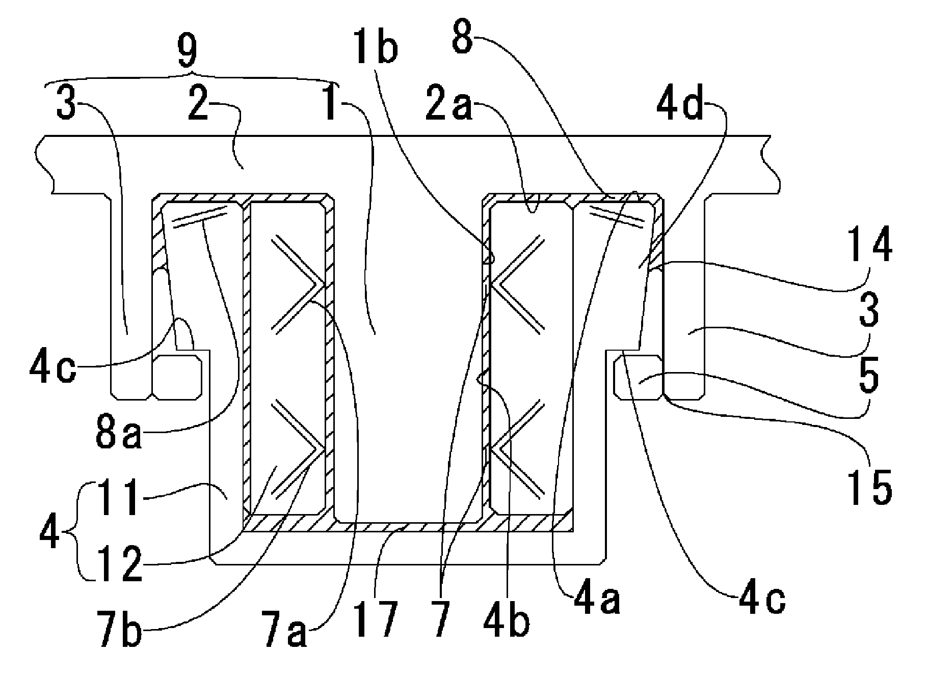
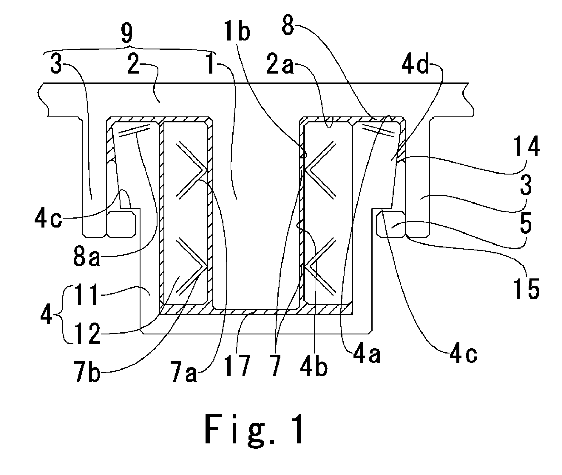
[0037]FIG. 1 shows a fluid dynamic bearing manufactured by the manufacturing method according to the invention.

[0038]The fluid dynamic bearing comprises a rotor hub 2 making up a shaft base. A shaft 1 and a cylindrical peripheral wall 3 are erected from the rotor hub 2. The shaft 1 and the cylindrical peripheral wall 3 make up a rotational member 9 together ...


PUM

PropertyMeasurementUnit
inner diameteraaaaaaaaaa
axial thicknessaaaaaaaaaa

Abstract

A method of manufacturing a fluid dynamic bearing in which a stopper is fixed by welding. The bearing comprises a hub, a shaft erected on the hub, a sleeve, a cylindrical wall erected on the hub, and the stopper mounted on the cylindrical wall. The method comprises a first step to hold oil in the bearing gap, and a second step to locate the stopper on the peripheral wall being apart from the interface of the oil to fix the stopper by LASER welding.

Description

FIELD OF THE INVENTION[0001]The present invention relates to a method of manufacturing a fluid dynamic bearing, or in particular to a method of manufacturing a fluid dynamic bearing used for a compact motor required to operate quietly at high speed such as a spindle motor for rotating the recording disk.BACKGROUND INFORMATION[0002]In recent years, quietude has been increasingly required of the recording disk drive unit including a hard disk with the increase in the rotational speed. For this reason, the fluid dynamic bearing has come to be widely used for the hard disk drive. The fluid dynamic bearing is configured of a fixed member and a rotational member. The fixed member and the rotational member are arranged in opposed relation, without mutual contact, to each other through a very small bearing gap. A lubricating fluid is filled in the bearing gap and the rotational member is rotatably supported on the fixed member by the dynamic pressure generated in the lubricating fluid.[0003...

Claims


Application Information

Patent Timeline
Patent Type & Authority Patents(United States)
IPC IPC(8): G11B17/02F16C32/06F16C17/10B23K26/28F16C33/10F16C33/74F16C35/02F16C43/02G11B19/20H02K5/16H02K7/08H02K21/22
CPCF16C43/02G11B19/2009B23K26/28F16C33/1045F16C33/745F16C17/107B23K2201/00Y10T29/49639F16C2370/12Y10T29/49636B23K2101/00F16C2226/36
Inventor INOUE, KIYOFUMIHAMADA, KATSUTOSHIUENOSONO, KAORU
Owner NIDEC CORP
Why Eureka
Try Eureka