Variable phase turbine

Active Publication Date: 2006-08-22
ENERGENT CORP
View PDF4 Cites 33 Cited by
  • Summary
  • Abstract
  • Description
  • Claims
  • Application Information

AI Technical Summary

Benefits of technology

[0014]c) pump means associated with the driven structure to effect second fluid flow along a second p

Problems solved by technology

That is, a turbine designed to be gas driven is not readily usable for liquid or two-phase flow.
For example attempts to use radial inflow gas turbines for two-phase flow have resulted in poor performance and damage because the

Method used


Image

  • Variable phase turbine
  • Variable phase turbine
  • Variable phase turbine

Examples


Embodiment Construction

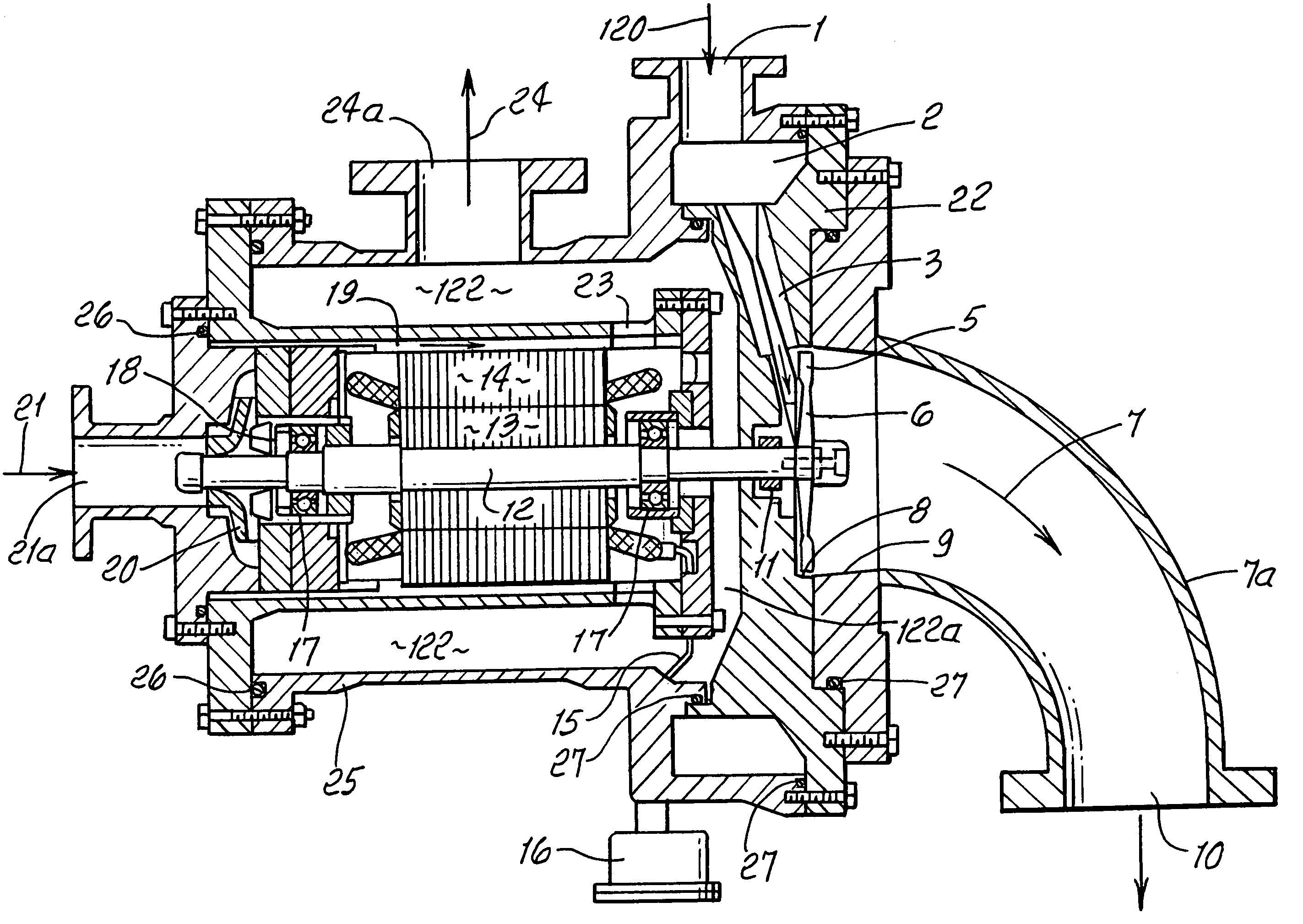
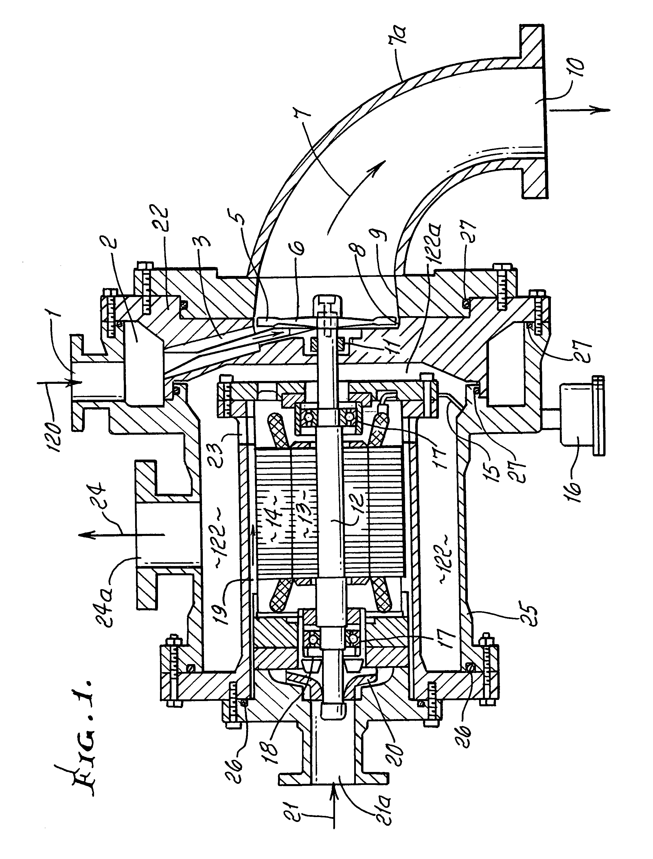
[0034]Referring to FIG. 1, gas, liquid or a mixture of the two (collectively and individually hereafter referred to as “fluid”) is introduced at 120 to the VPTRA through an inlet 1. The fluid is collected in a manifold 2, and flows to a multiplicity of nozzle inserts 3, which are easily replaceable. The nozzle inserts are arranged in a holder 22, to direct the fluid in a generally tangential direction towards rotor blades 5. The rotor 6 is carried by a rotatably driven shaft 12.

[0035]The fluid is expanded from the inlet pressure to a lower pressure in the nozzle inserts, producing a jet having kinetic energy. The jet is impinged upon impulse blades 5, which act to reverse the direction of flow, producing force on the blades. The blades are attached to rotor 6, and are easily replaceable. The blades transmit the force to the rotor producing a torque on the shaft 12 causing rotation.

[0036]The rotation drives an electric rotor piece 13 which is attached to the shaft, producing generate...


PUM


Abstract

An axial flow turbine configured to accept different nozzles which are respectively compatible with different fluids (gas, liquid or mixture thereof). The turbine is compatible with different rotating loads, which can be cooled or lubricated using liquid derived from the fluid.

Description

BACKGROUND OF THE INVENTION[0001]This invention relates generally to fluid driven turbines, and more particularly to what are described herein as variable phase fluid driven turbines.[0002]Turbines are widely used in industry to convert the energy in liquid streams or gas streams to shaft power. Less common, but also used are turbines to convert the energy in two-phase (gas and liquid) streams to shaft power. The turbines for each type of stream are unique to that stream. That is, a turbine designed to be gas driven is not readily usable for liquid or two-phase flow. For example attempts to use radial inflow gas turbines for two-phase flow have resulted in poor performance and damage because the direction of centrifugal body forces is such as to throw liquid backwards into the nozzle blades.[0003]Certain application for turbines require the use of different types of fluid streams for differing conditions. For example, a low temperature geothermal power system may require use of a ga...

Claims


Application Information

Patent Timeline
IPC IPC(8): G01F1/05
CPCF01D1/20F02C1/05F05D2210/13
Inventor HAYS, LANCE G.SAHABIAN, DICRAN
Owner ENERGENT CORP
Why Eureka
Try Eureka