Grinding disc structure

a technology of grinding discs and discs, which is applied in the direction of gear teeth, manufacturing tools, manufacturing apparatuses for gear teeth, etc., can solve the problems of troublesome assembly of these components, prolonging assembly time, and affecting the health of operators, etc., and achieves the effect of improving the grinding disc structur

Inactive Publication Date: 2006-08-22
CHANG JEN PEN
View PDF4 Cites 30 Cited by
  • Summary
  • Abstract
  • Description
  • Claims
  • Application Information

AI Technical Summary

Problems solved by technology

This is harmful to the health of an operator.
It is troublesome to assemble these components.
This prolongs the assembling time.

Method used


Image

  • Grinding disc structure
  • Grinding disc structure
  • Grinding disc structure

Examples


Embodiment Construction

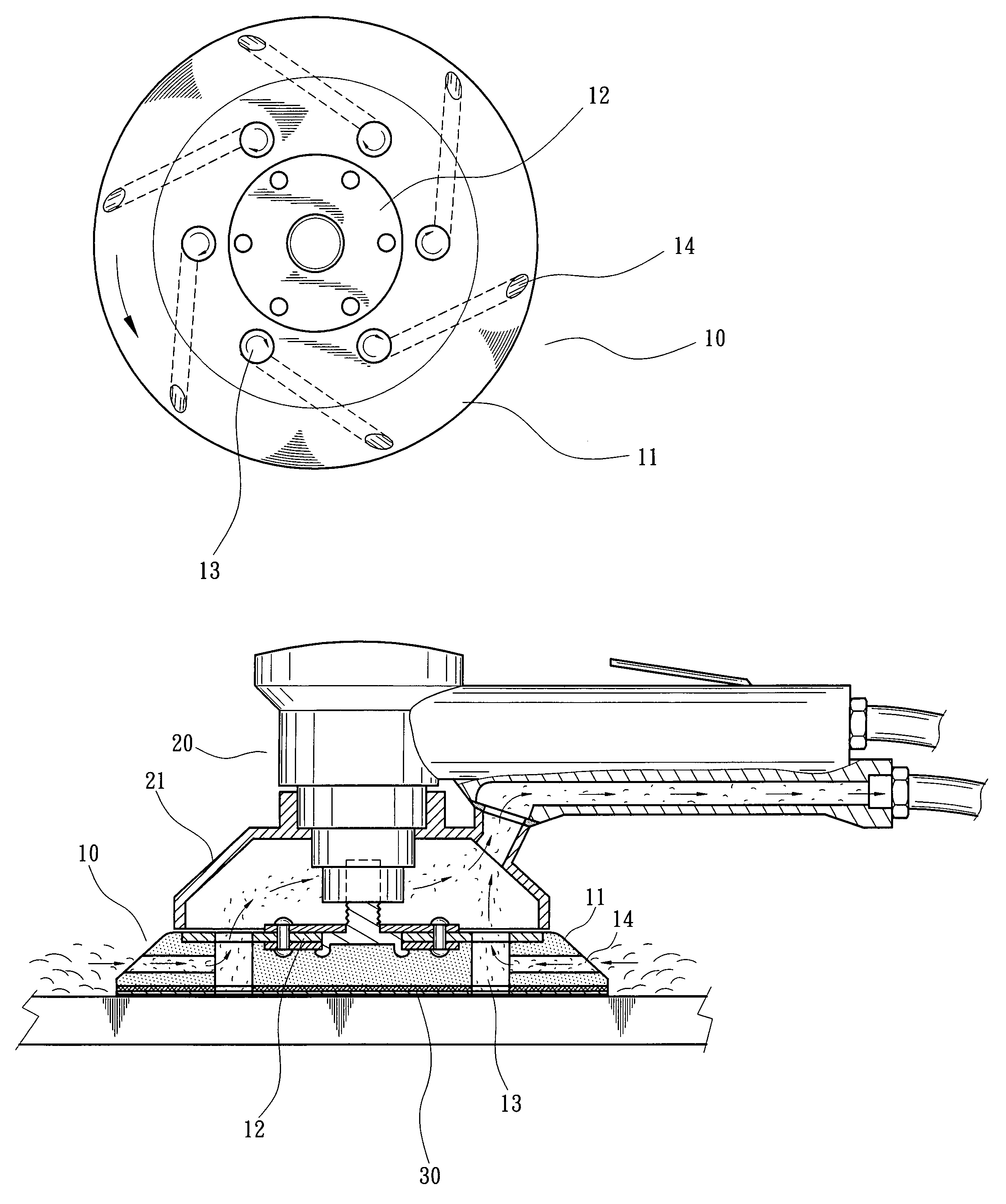
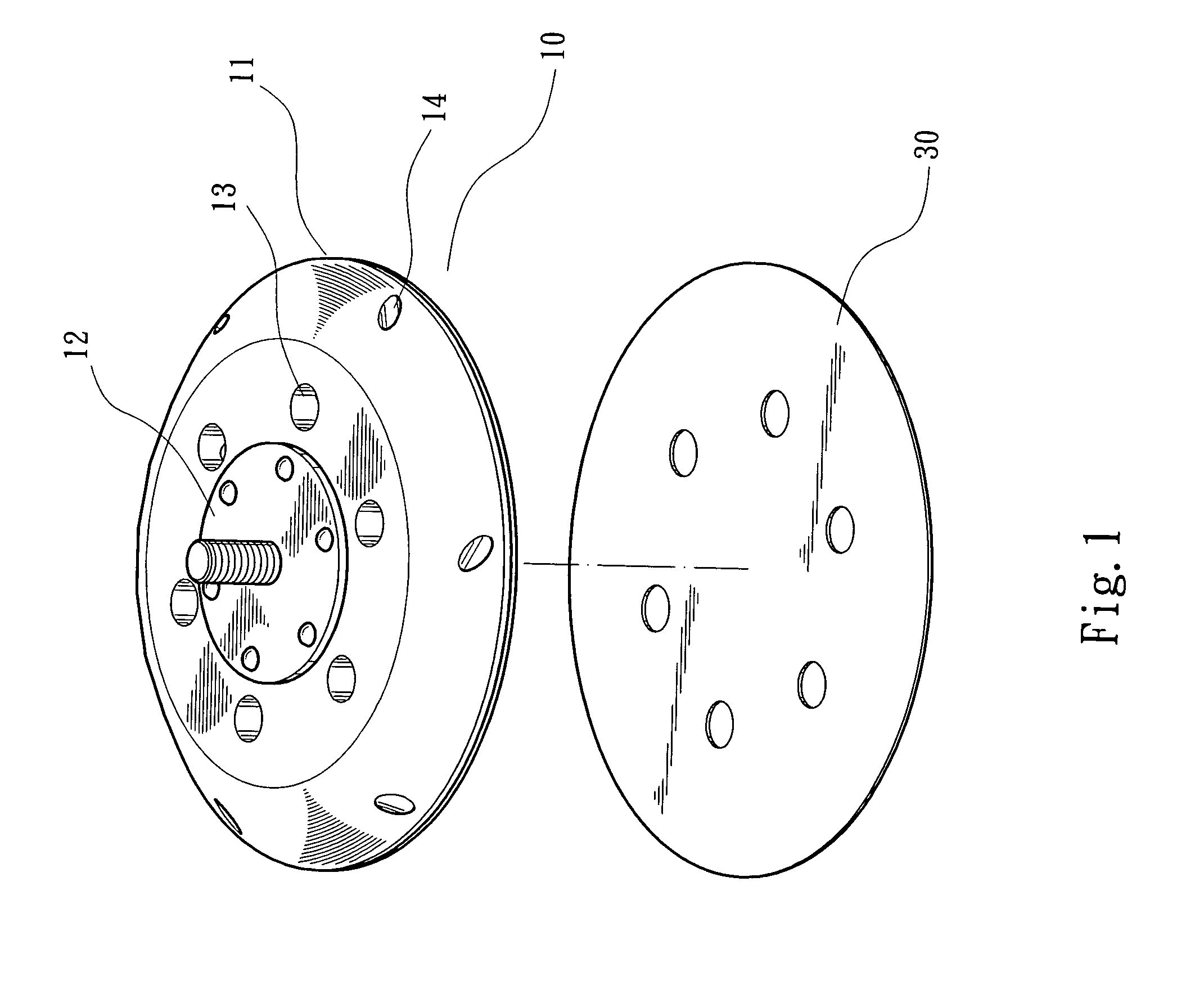
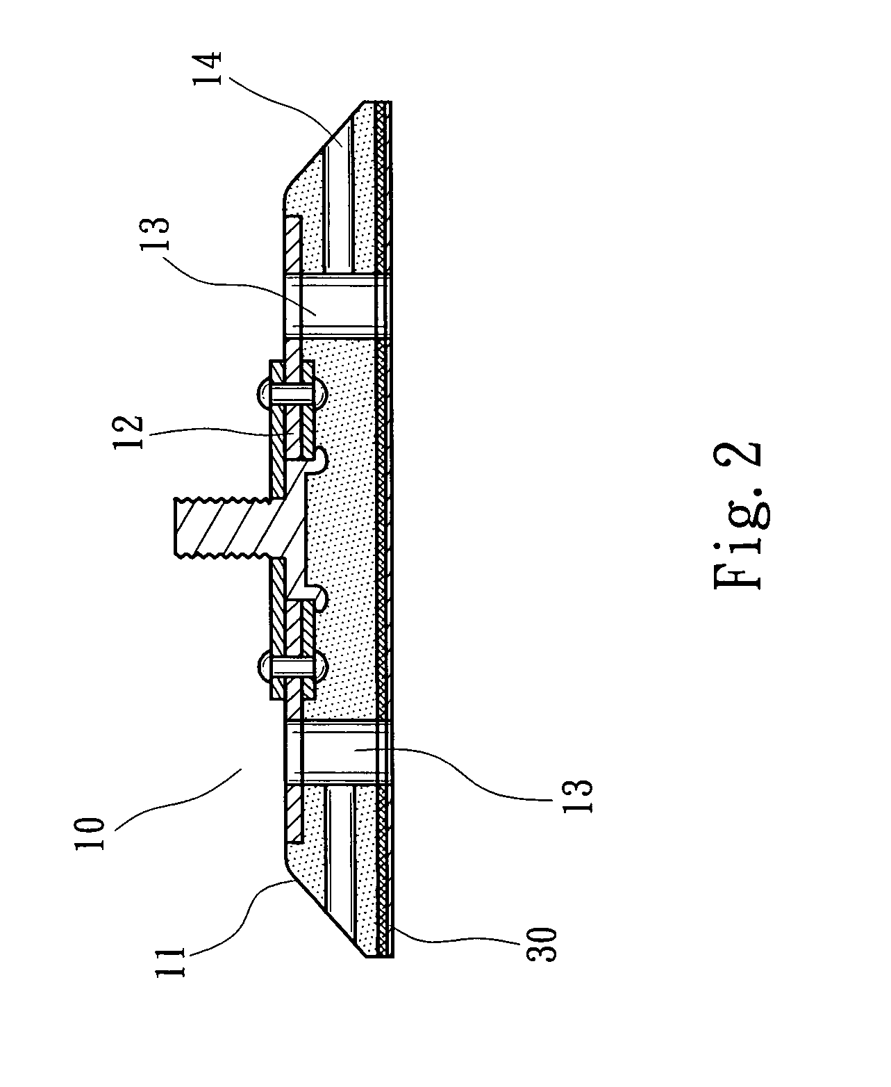
[0014]Please refer to FIGS. 1 and 2. The grinding disc 10 of the present invention includes a main disc 11 having a central section 12 for connecting with a grinder 20 and a cover body 21 (as shown in FIG. 4). The main disc 11 has multiple through holes 13 nearly in parallel to the axis of the main disc 11. At least one end of each through hole 13 communicates with the cover body 21, whereby the airflow, powder or dust can be sucked and exhausted through the cover body 21. The main disc 11 is formed with multiple internal passages 14 respectively corresponding to the through holes 13. The passages 14 are horizontally formed and nearly perpendicular to the axis of the main disc 11. Two ends of each passage 14 respectively communicate with the through hole 13 and outer side around the main disc 11.

[0015]FIG. 3 shows that the passages 14 are tangential to the through holes 13. When the external grinding powder or dust is sucked from outer end of the passage 14 into the through hole 13,...


PUM


Abstract

A grinding disc structure including an integrally formed main disc adapted to a dust-sucking cover body of a grinder. The main disc has multiple through holes nearly in parallel to an axis of the main disc. The main disc is further formed with multiple internal passages which are horizontally formed in the main disc corresponding to the through holes and nearly perpendicular to the axis of the main disc. The passages are tangential to the through holes. Two ends of each passage respectively communicate with the through hole and outer side around the main disc. The main disc has a complete bottom face to which a grinding layer can be fully adhered.

Description

BACKGROUND OF THE INVENTION[0001]The present invention is related to an improved grinding disc structure in which the main disc is integrally formed to simplify the assembling procedure of the grinding disc.[0002]A conventional grinder is used to grind and buff a work piece. In grinding operation, powders and dusts are produced to contaminate the environment. This is harmful to the health of an operator.[0003]Taiwanese Patent Application No. 91207022, entitled “grinding disc structure” discloses a grinder with dust-exhausting effect. The grinder includes a main disc 20 formed with an annular groove 21. The annular groove 21 communicates with several guide channels 22 arranged at equal angular intervals. The main disc 20 is further formed with several dust-exhausting holes 73. The grinder further includes a substrate 10 formed with several through holes 12 communicating with the interior of a cover body 53. A grinding layer 40 is adhered to or connected with the main disc 20. The gri...

Claims


Application Information

Patent Timeline
Patent Type & Authority Patents(United States)
IPC IPC(8): B24B23/00B24B23/02B24D3/00
CPCB24D9/085B24B55/10
Inventor CHANG, JEN-PEN
Owner CHANG JEN PEN
Why Eureka
Try Eureka