Distal protection device and method

a protection device and distal valve technology, applied in the field of distal valve protection devices, can solve problems such as occlude distal vasculature, thrombosis can be particularly problematic, and problems may be encountered during thrombosis

Inactive Publication Date: 2006-08-22
BOSTON SCI SCIMED INC
View PDF331 Cites 247 Cited by
  • Summary
  • Abstract
  • Description
  • Claims
  • Application Information

AI Technical Summary

Problems solved by technology

Thrombus formation can be particularly problematic in a saphenous vein graft (“SVG”).
However, problems may be encountered during thrombectomy and atherectomy because the stenotic debris which is separated from the stenosis is free to flow within the lumen of the vessel.
If the debris flows distally, it can occlude distal vasculature and cause significant problems.
If it flows proximally, it can enter the circulatory system and form a clot in the neural vasculature or in the lungs, both of which are highly undesirable.
However, this technique has certain problems.
For instance, it is difficult to control the size of the fragments which are severed from the stenotic lesion.
Larger fragments may be severed accidentally.
Also, since thrombus is much softer than an atheroma, it tends to break up easier when mechanically engaged by a cutting instrument.
Therefore, at the moment that the thrombus is mechanically engaged, there is a danger that it can be dislodged in large fragments which would occlude the vasculature.
However, it may be necessary to pull quite a high vacuum in order to remove all of the pieces severed from the stenosis.
If the vacuum used is not high enough, all of the severed pieces will not be removed.
Further, use of a high vacuum may tend to cause the vasculature to collapse.
Problems are also associated with this technique.
For example, delivery of such devices in a low-profile pre-deployment configuration can be difficult.
Further, some devices include complex and cumbersome actuation mechanisms.
Also, retrieving such capture devices, after they have captured emboli may be difficult.

Method used


Image

  • Distal protection device and method
  • Distal protection device and method
  • Distal protection device and method

Examples


Embodiment Construction

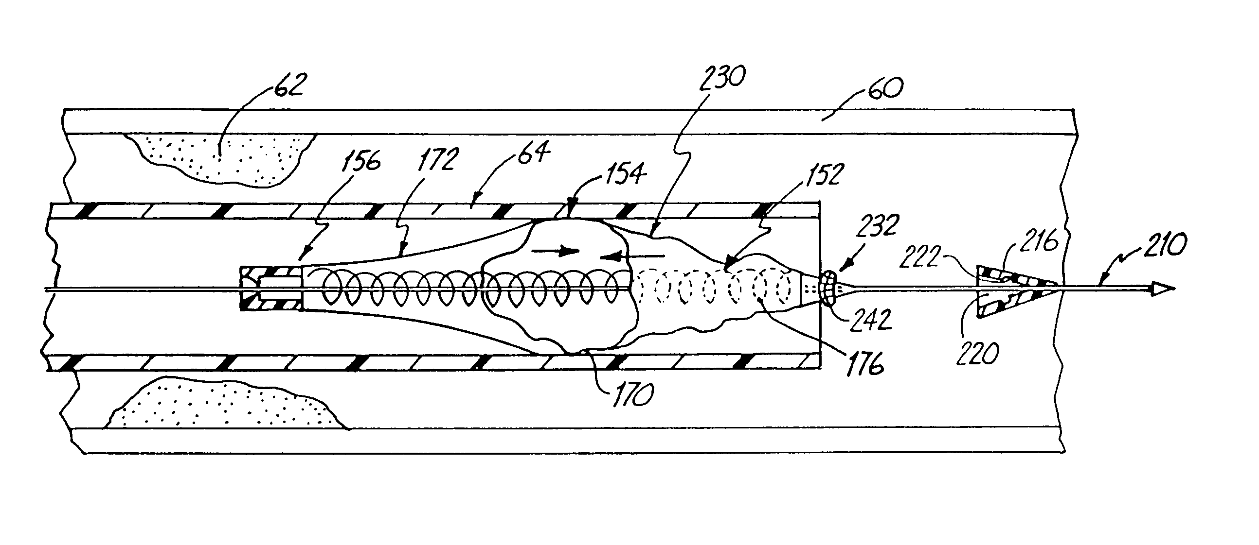
[0035]The present invention relates to protection devices deployed in a body vessel or cavity for collection of loosened or floating debris such as embolic material dislodged during atherectomy or thrombectomy.

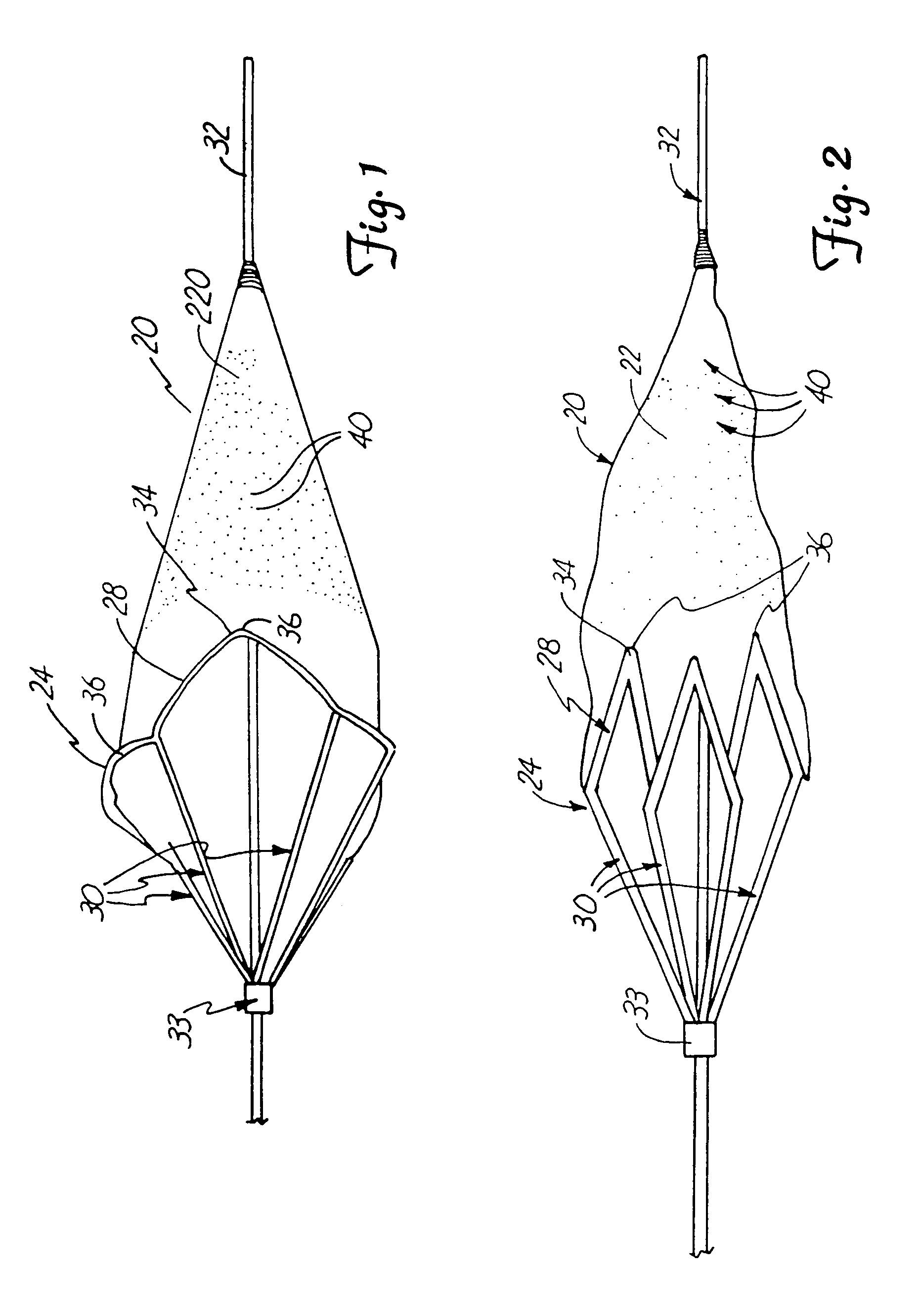
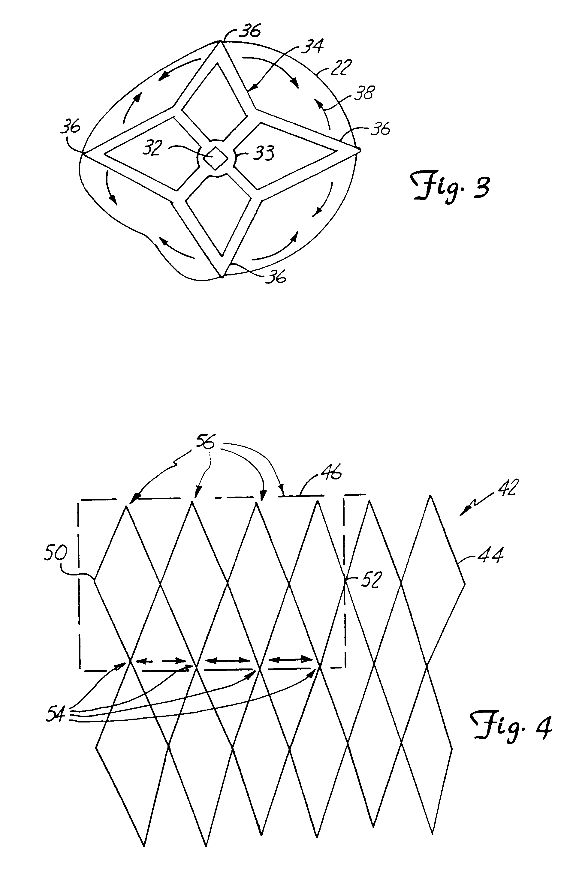
[0036]FIGS. 1–7 illustrate an embodiment of a protection device 20 or filter for collecting loosened debris in a body lumen. As illustrated comparatively in FIGS. 1–2, device 20 operates between a closed collapsed profile, adapted for insertion into a body lumen as illustrated in FIG. 2, and an open radially-expanded deployed profile for collecting debris in a body lumen as illustrated in FIG. 1.

[0037]Device 20 includes a filter 22 and a collapsible proximally-tapered frame 24. Frame 24 supports filter 22 and is operably coupled to an elongated guidewire 32 or other support device. Frame 24 includes a mouth 28 and a plurality of longitudinally-extending ribs 30. In an expanded profile, mouth 28 is opened and the ribs extend radially outwardly to support mouth 28. Preferably, a...


PUM


Abstract

A device adapted for deployment in a body vessel for collecting floating debris and emboli in a filter. The device includes a collapsible proximally tapered frame for operably supporting the filter between a collapsed insertion profile and an expanded deployment profile. The tapered collapsible frame includes a mouth which is sized to extend to walls of the body vessel in the expanded deployed profile to seal the filter relative to the body vessel for collecting debris floating in the body vessel.

Description

CROSS-REFERENCE TO RELATED APPLICATION[0001]This application is a CIP of application Ser. No. 08 / 943,358, filed Oct. 3, 1997 now U.S. Pat. No. 6,081,118, entitled DISTAL PROTECTION DEVICE AND METHOD and assigned to the same assignee as the present invention, which is a CIP of application Ser. No. 08 / 810,825 filed Mar. 6, 1997 now U.S. Pat. No. 5,814,064, entitled DISTAL PROTECTION DEVICE and assigned to the same assignee as the present invention.BACKGROUND OF THE INVENTION[0002]The present invention deals with an emboli capturing system. More specifically, the present invention deals with an emboli capturing system and method for capturing embolic material in a blood vessel during an atherectomy or thrombectomy procedure.[0003]Blood vessels can become occluded (blocked) or stenotic (narrowed) in a number of ways. For instance, a stenosis may be formed by an atheroma, which is typically a harder, calcified substance which forms on the lumen walls of the blood vessel. A stenosis may a...

Claims


Application Information

Patent Timeline
Patent Type & Authority Patents(United States)
IPC IPC(8): A61M29/00A61B17/00A61B17/22A61F2/00A61F2/01
CPCA61B17/221A61F2/01A61F2/013A61F2230/0067A61B2017/22038A61B2017/22042A61B2017/22049A61B2017/22061A61B2017/2212A61F2002/30092A61F2210/0014A61M2025/09125A61M2025/09183A61F2002/018A61F2230/0006A61F2230/0008A61F2230/005A61B2017/00539A61F2/0105A61F2/0108
Inventor BROOME, THOMAS E.DANIEL, JOHN M. K.HEKTNER, THOMAS R.
Owner BOSTON SCI SCIMED INC
Why Eureka
Try Eureka