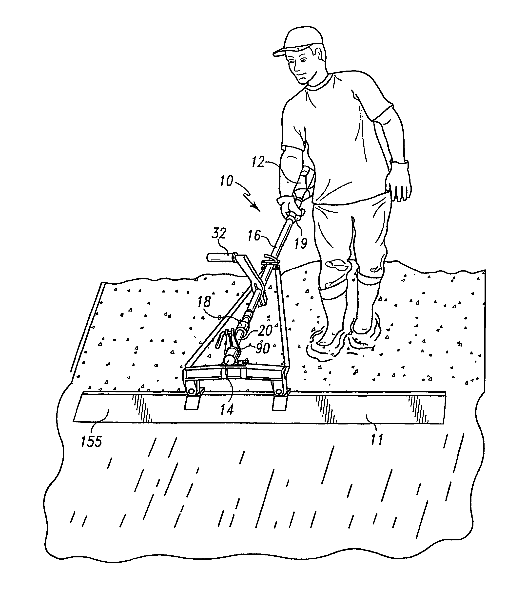
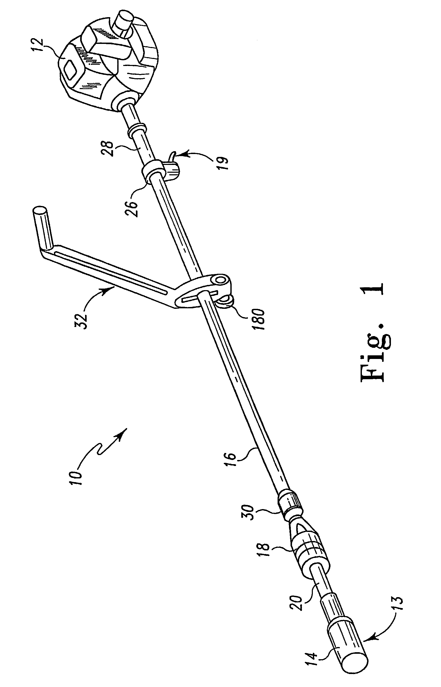
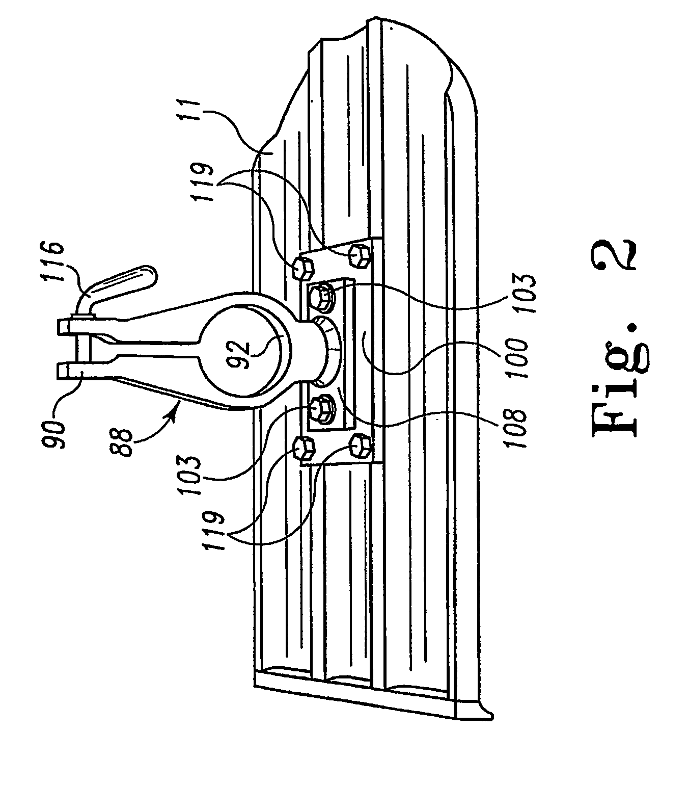
Universal power unit that adapts to all phases from placing to final finishing of concrete
a power unit and power supply technology, applied in the direction of engines/engines, machines/engines, engines, etc., can solve the problems of small gas-powered engines not turning enough rpm to damage sealed bearings, and limit the eccentric used for vibration, so as to reduce vibrations
- Summary
- Abstract
- Description
- Claims
- Application Information
AI Technical Summary
Problems solved by technology
Method used
Image
Examples
first embodiment
[0060]Proximal flange 36, central flange 38, distal plate 34, proximal rubber portion 42 and distal rubber portion 40 are each formed to include a plurality of fastener-receiving holes 54. In the illustrated embodiment, four fastener receiving-holes 54, each displaced ninety degrees from its adjacent fastener-receiving holes 54, are formed in each of proximal flange 36, central flange 38, distal plate 34, proximal rubber portion 42 and distal rubber portion 40. When assembled, the fastener-receiving holes 54 in proximal flange 36, central flange 38, distal plate 34, proximal rubber portion 42 and distal rubber portion 40 are aligned to facilitate passage of the shafts of fasteners 44 through proximal flange 36, central flange 38, distal plate 34, proximal rubber portion 42 and distal rubber portion 40. In the illustrated first embodiment of isolation unit 18, four fasteners 44 secure the components of isolation unit 18 together. Each illustrated fastener 44 is bolt with a threaded s...
second embodiment
[0064]isolation unit 518 is shown in FIGS. 7–9. Illustratively, isolation unit 518 includes a proximal plate 534, a distal plate 536, a central plate 538, a proximal rubber portion 540, a distal rubber portion 542 and a plurality of fasteners 544 coupling proximal plate 534 to distal plate 536. Proximal rubber portion 540 is disposed between proximal plate 534 and central plate 538. Illustratively, proximal rubber portion 540 is glued to both proximal plate 534 and central plate 538. However, it is within the teaching of the disclosure for proximal rubber portion 540 to be otherwise affixed to one or both of proximal plate 534 and central plate 538 using bonding techniques or adhesives or merely engage one or both of proximal plate 534 or central plate 538. Distal rubber portion 542 is disposed between distal plate 536 and central plate 538. Illustratively, distal rubber portion 542 is glued to both distal plate 536 and central plate 538. However, it is within the teaching of the di...
third embodiment
[0069]isolation unit 618 is shown in FIG. 29. Isolation unit 618 is formed by integrally molding a rubber portion 642 to a proximal flange 636 on a proximal housing 635 and a distal flange 638 on a distal housing 637.
[0070]In the illustrated embodiment, proximal housing 635 is frusto-conically shaped and includes a central longitudinally extending aperture 645 sized to receive distal end 30 of first rigid shaft case portion 16 therein. In the illustrated embodiment, proximal housing 635 is molded from aluminum or an aluminum alloy.
[0071]Rubber portion 642 is disposed between proximal flange 636 and distal flange 638. Illustratively, rubber portion 642 is cylindrical shaped with a central longitudinal aperture 646 extending longitudinally therethrough. Rubber portion 642 is molded to distal flange 638 and proximal flange 636. However, it is within the teaching of the disclosure for rubber portion 642 to be otherwise affixed to distal flange 638 and proximal flange 636 using bonding t...
PUM
 Abstract
Description
Claims
Application Information
 - R&D
- Intellectual Property
- Life Sciences
- Materials
- Tech Scout
- Unparalleled Data Quality
- Higher Quality Content
- 60% Fewer Hallucinations
Browse by: Latest US Patents, China's latest patents, Technical Efficacy Thesaurus, Application Domain, Technology Topic, Popular Technical Reports.
© 2025 PatSnap. All rights reserved.Legal|Privacy policy|Modern Slavery Act Transparency Statement|Sitemap|About US| Contact US: help@patsnap.com


