Multi-coil coupling system for hearing aid applications

a coupling system and hearing aid technology, applied in the direction of deaf-aid sets, electrical equipment, electronic input selection/mixing, etc., can solve the problems of high background noise, hearing impaired individuals often have great difficulty carrying on normal conversations in noisy environments, and may require a hearing solution

Inactive Publication Date: 2006-08-29
III HLDG 7
View PDF16 Cites 51 Cited by
  • Summary
  • Abstract
  • Description
  • Claims
  • Application Information

AI Technical Summary

Benefits of technology

[0061]FIG. 36 illustrates an additional embodiment in which a hearing improvement device i

Problems solved by technology

In many situations, however, hearing impaired individuals may require a hearing solution beyond that which can be provided by such a hearing aid using it's internal microphone alone.
For example, hearing impaired individuals often have great difficulty carrying on normal conversations in noisy environments, such as parties, meetings, sporting events or the like, involving a high level of background noise.
In addition, hearing impaired individuals also often have difficulty listening to audio sources located at a distance from the individual, or to several audio sources located at various distances from the individual and at various positions relative to the individual.
The characteristics and location of a hearing aid internal microphone often results in excessive pickup of ambient acoustical noise.
A common problem with prior art tele-couplers of the neck loop and silhouette styles has been the difficulty of bathing the telecoil in a magnetic field that is both of suffic

Method used


Image

  • Multi-coil coupling system for hearing aid applications
  • Multi-coil coupling system for hearing aid applications
  • Multi-coil coupling system for hearing aid applications

Examples


Embodiment Construction

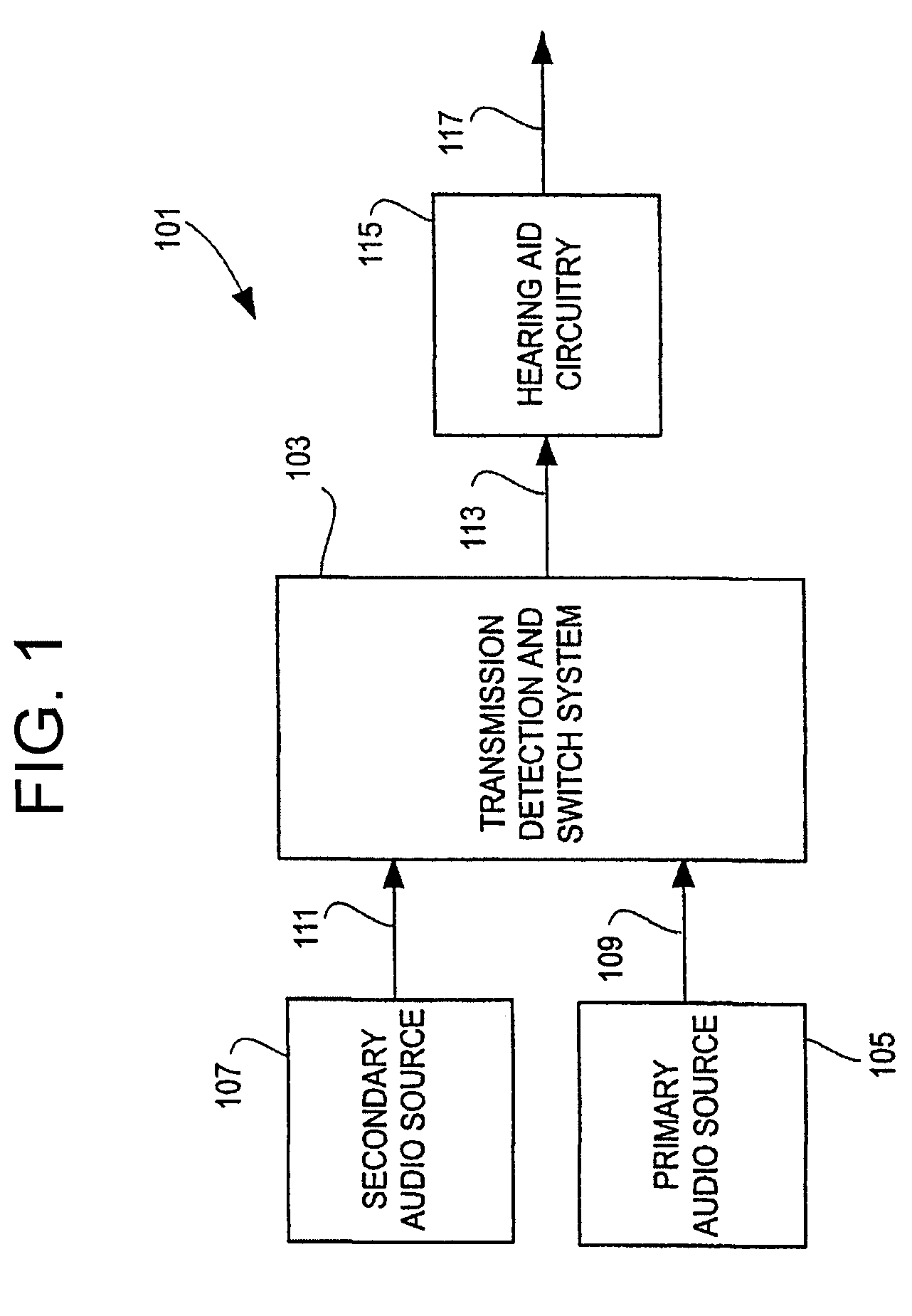
[0062]FIG. 1 is a block diagram of an overall hearing improvement system 101 of the present invention. A transmission detection and switch system 103 receives signals from both a primary audio source 105 and a secondary audio source 107. The primary audio source 105 may be, for example, a directional or omnidirectional microphone located in a hearing aid. The secondary audio source 107 may be, for example, a directional microphone / transmitter mounted on eyeglasses (or otherwise supported by a hearing aid user), a television or stereo transmitter, a telephone or a microphone / transmitter combination under the control of a talker. In one embodiment, the secondary audio source 107 utilizes a wireless transmission scheme for transmission of signals to the transmission detection and switch system 103. In another embodiment, the secondary audio source 107 is wired to the transmission detection and switch system 103.

[0063]In operation, the transmission detection and switch system 103, which...


PUM


Abstract

A hearing improvement device using a multi-coil coupling system and methods for operating such a device are disclosed. An embodiment of the present invention may use an array microphone to provide highly directional reception. The received audio signal may be filtered, amplified, and converted into a magnetic field for coupling to the telecoil in a conventional hearing aid. Multiple transmit inductors may be used to effectively couple to both in-the-ear and behind-the-ear type hearing aids, and an additional embodiment is disclosed which may be used with an earphone, for users not requiring a hearing aid.

Description

CROSS-REFERENCE TO RELATED APPLICATIONS / INCORPORATION BY REFERENCE[0001]This application is a continuation in part of U.S. application Ser. No. 09 / 752,806, “Transmission Detection and Switch System for Hearing Improvement Applications,” filed on Dec. 28, 2000, U.S. Pat. No. 6,694,034, which is incorporated herein by reference in its entirety, and which makes reference to, and claims priority to, U.S. provisional applications Ser. No. 60 / 174,958 filed Jan. 7, 2000 and Ser. No. 60 / 225,840 filed Aug. 16, 2000.[0002]The above-referenced U.S. provisional applications Ser. No. 60 / 174,958, Ser. No. 60 / 225,840, and Ser. No. 60 / 123,004 are hereby incorporated herein by reference in their entirety. U.S. Pat. No. 6,009,311 is hereby incorporated herein by reference in its entirety.FEDERALLY SPONSORED RESEARCH OR DEVELOPMENT[0003][N / A]MICROFICHE / COPYRIGHT REFERENCE[0004][N / A]BACKGROUND OF THE INVENTION[0005]Numerous types of hearing aids are known and have been developed to assist individuals w...

Claims


Application Information

Patent Timeline
IPC IPC(8): H04R25/00
CPCH04R25/43H04R25/554H04R25/502H04R2225/61H04R2225/51H04R25/552H04R25/603
Inventor JULSTROM, STEPHEN D.DRAMBAREAN, VIORELSOEDE, WILLEM
Owner III HLDG 7
Why Eureka
Try Eureka