Flexural plate wave sensor

a technology of flexural plate and wave sensor, which is applied in the direction of fluid pressure measurement, generator/motor, instruments, etc., can solve the problems of increasing the design complexity and the operation of the prior art calculated gains, etc., and achieves the reduction of the number of eigenmodes excited, simplifying the operation and design of the flexural plate wave sensor, and simplifying the effect of eigenmodes excited

Inactive Publication Date: 2006-09-19
CHARLES STARK DRAPER LABORATORY
View PDF8 Cites 13 Cited by
  • Summary
  • Abstract
  • Description
  • Claims
  • Application Information

AI Technical Summary

Benefits of technology

[0006]It is a further object of this invention to provide such a sensor which reduces the number of eigenmodes excited in the flexural plate.
[0023]This invention further features a flexural wave plate sensor with a flexural plate having a length and a width, and a comb pattern over the flexural plate. The comb pattern may include a set of drive teeth and a set of sense teeth. The set of drive teeth and the set of sense teeth may be disposed over the flexural plate. The drive teeth may span approximately fifty percent of the length of the flexural plate, and the sense teeth may span approximately fifty percent of the length of the flexural plate. Ideally, the comb pattern reduces the number of eigenmodes excited in the plate and thereby simplifying the operation and design of the flexural plate wave sensor.

Problems solved by technology

A significant drawback of prior designs is that the increased number of eigenmodes excited in the FPW sensor produces a series of resonance peaks of similar amplitude and irregular phase which increases design complexity and the operation of the prior art flexure plate wave sensors.
Moreover, prior art flexural plate wave sensors utilize drive and sense combs at opposite ends of the flexural plate and rely on analysis based on an analogy to surface acoustic waves (SAW) wherein the waves propagate away from the drive combs and toward the sense combs and back reflections are regarded as interference.
A distinct disadvantage of this analysis is that SAW theory does not account for numerous small peaks produced by the sensor resulting in calculated gains (e.g., peaks of similar magnitude) which are low and do not account for sharp phase drops seen with the peaks (e.g., irregular phase).

Method used


Image

  • Flexural plate wave sensor
  • Flexural plate wave sensor
  • Flexural plate wave sensor

Examples


Embodiment Construction

[0050]Aside from the preferred embodiment or embodiments disclosed below, this invention is capable of other embodiments and of being practiced or being carried out in various ways. Thus, it is to be understood that the invention is not limited in its application to the details of construction and the arrangements of components set forth in the following description or illustrated in the drawings.

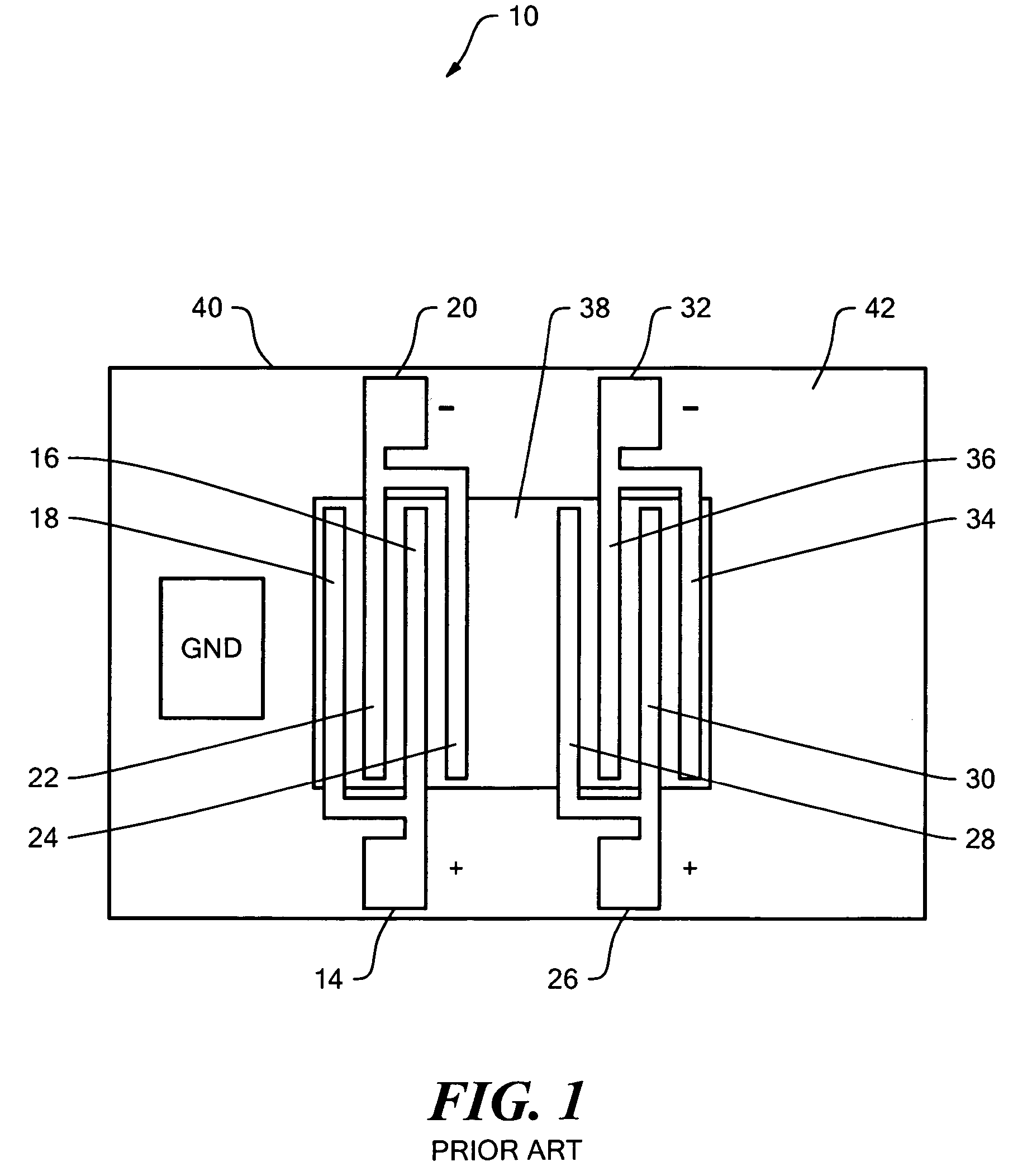
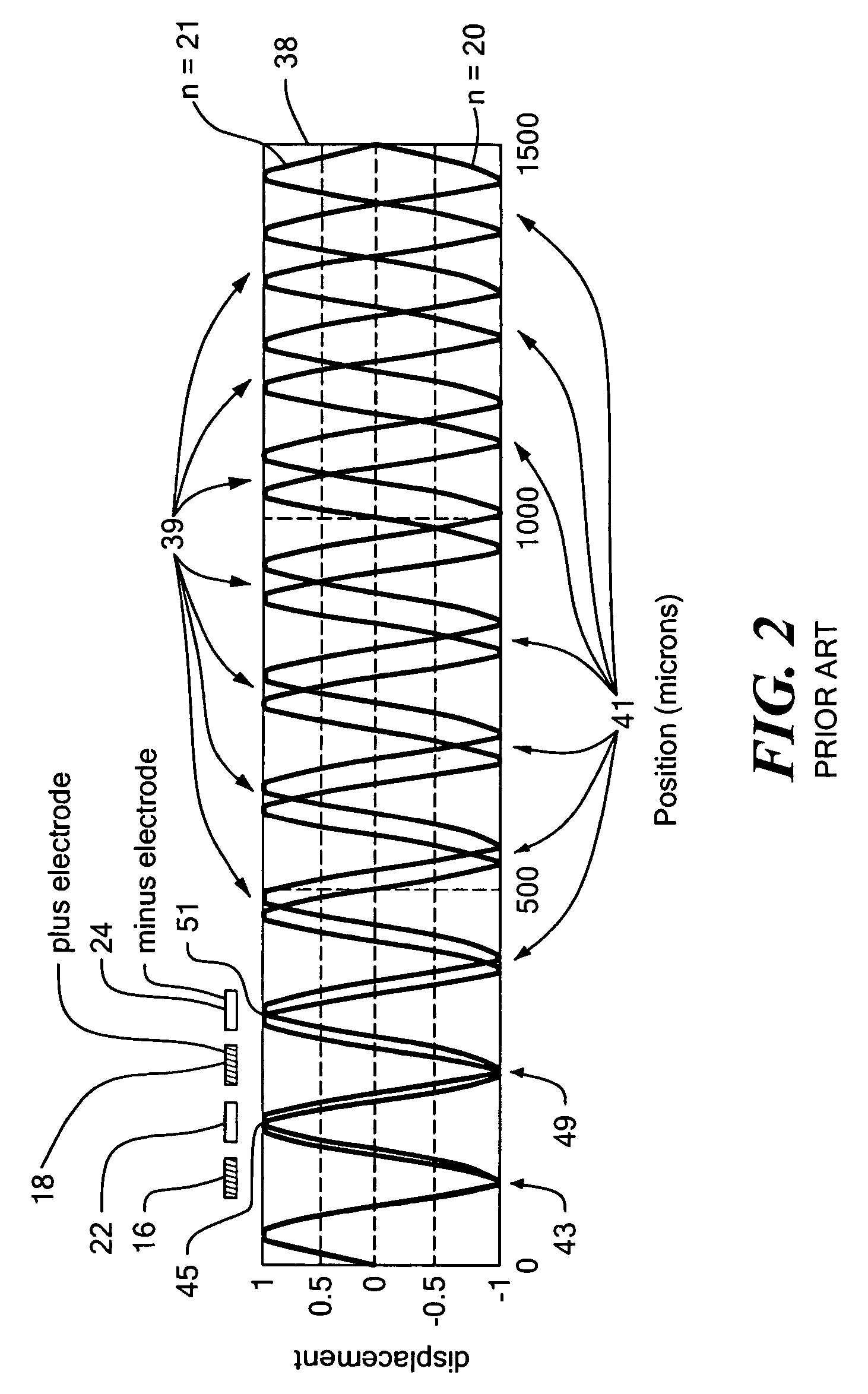
[0051]As discussed in the Background section above, prior art flexure plate wave sensor 10, FIG. 1 includes drive comb 14 with drive teeth 16 and 18 and drive comb 20 with drive teeth 22 and 24. Typically, drive combs 14 and 20 are driven at opposite polarity, e.g., drive comb 14 is driven at a positive polarity and drive comb 20 is driven at a negative polarity, to align with the positive and negative peaks of the eigenmodes.

[0052]As shown in FIG. 1, drive combs 14 and 20 are disposed over only approximately twenty-five to forty percent of the entire length of flexural plate 38. Because of...


PUM

PropertyMeasurementUnit
thickaaaaaaaaaa
thickaaaaaaaaaa
thickaaaaaaaaaa

Abstract

A flexural plate wave sensor including a flexural plate having a length and a width and a comb pattern over the flexural plate with drive teeth disposed across the entire length of the flexural plate to reduce the number of eigenmodes excited in the plate and thereby simplifying the operation and design of the flexure plate wave sensor.

Description

FIELD OF THE INVENTION[0001]This invention relates generally to flexure plate wave sensors and more particularly to an improved comb pattern for a flexural plate wave sensor.BACKGROUND OF THE INVENTION[0002]A flexural plate wave (FPW) sensor includes a diaphragm or plate which is driven so it oscillates at frequencies determined by a comb pattern and the flexural plate geometry. The comb pattern is disposed over the flexural plate and establishes electric fields which interact with the plate's piezoelectric properties to excite motion. The eigenmodes describe the diaphragm displacements which exhibit spatially distributed peaks. Each eigenmode consists of n half sine periods along the diaphragm's length. A typical FPW sensor can be excited to eighty or more eigenmodes. In a typical FPW eigenmode, the plate deflection consists of many sinusoidal (or nearly sinusoidal) peaks.[0003]Prior art flexure plate wave sensors typically include drive combs at one end of the plate and sense comb...

Claims


Application Information

Patent Timeline
Patent Type & Authority Patents(United States)
IPC IPC(8): H01L41/08G01L9/00G01N29/02
CPCG01L9/0025G01N29/022Y10T29/42G01N2291/0427G01N2291/0423G01L9/00
Inventor WEINBERG, MARC S.CUNNINGHAM, BRIANHILDEBRANT, ERIC
Owner CHARLES STARK DRAPER LABORATORY
Why Eureka
Try Eureka