Anterior lumbar interbody fusion cage with locking plate

Active Publication Date: 2006-09-26
DEPUY ACROMED INC
View PDF56 Cites 251 Cited by
  • Summary
  • Abstract
  • Description
  • Claims
  • Application Information

AI Technical Summary

Benefits of technology

[0008]In another embodiment, the fusion cage includes an intermediate plane that separates the inferior face from the superior face to define an inferior side and a superior side, and the plate includes at least one inferior aperture on the inferior side of the fusion cage and at least one superior aperture on the superior side of the fusion cage. Each aperture in the plate can have a first end having an opening, a second, opposed end, and a sidewall extending therebetween that defines an inner lumen. The first end of each aperture preferably is a generally spherical recess formed in the plate for rotatably seating a head of a bone screw. A split bushing is preferably disposed

Problems solved by technology

Advancing age, as well as injury, can lead to changes in the bones, disks, j

Method used


Image

  • Anterior lumbar interbody fusion cage with locking plate
  • Anterior lumbar interbody fusion cage with locking plate
  • Anterior lumbar interbody fusion cage with locking plate

Examples


Example

DETAILED DESCRIPTION OF THE DRAWINGS

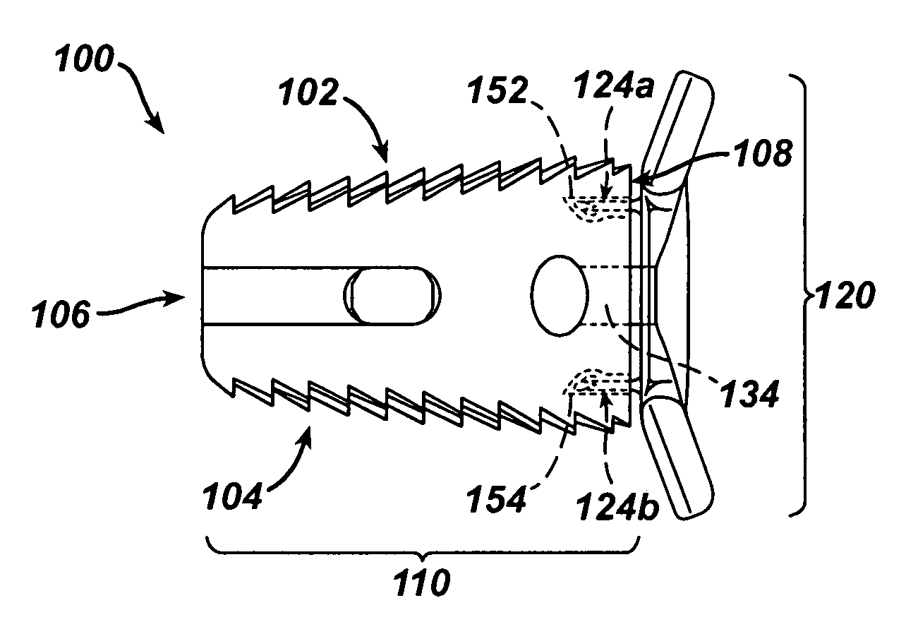
[0021]In general, the present invention provides a spinal fixation assembly including a fusion cage with posterior, anterior, superior, and inferior faces, and a plate having at least one aperture for receiving a bone screw and having a mating element adapted to slidably engage and mate to the anterior face of the fusion cage. The cage is adapted to be positioned between adjacent vertebrae, and the plate is effective to mate to the cage and to receive one or more bone screws to fasten the plate and secure the fusion cage to the adjacent vertebrae.

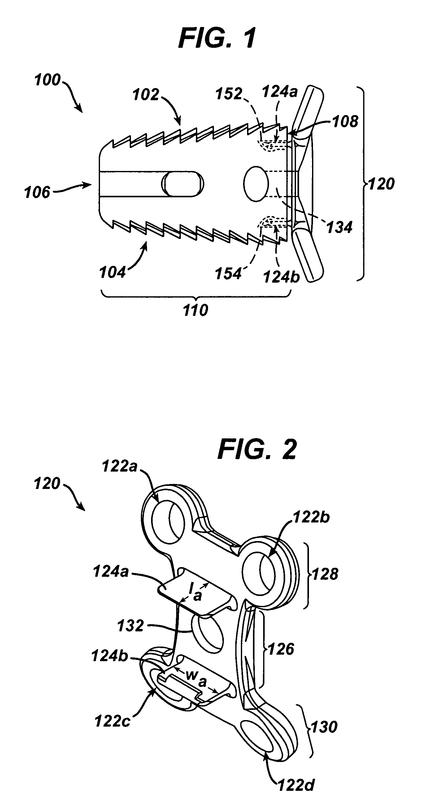
[0022]As shown in FIG. 1, the assembly 100 generally includes a fusion cage 110 and a plate 120 which slidably mates to the cage 110 in a superior / inferior direction. The fusion cage 110 includes superior 102, inferior 104, posterior 106 and anterior sides 108, and the plate 120 includes at least one aperture 122a–d (shown in FIG. 2) for receiving a bone screw. The plate 120 further includes a mating elem...


PUM


Abstract

A spinal fixation assembly is provided including a fusion cage with posterior, anterior, superior, and inferior faces, and a plate having at least one aperture for receiving a bone screw and having a mating element adapted to slidably engage and mate to the anterior face of the fusion cage. The cage is adapted to be positioned between adjacent vertebrae, and the plate is effective to mate to the cage and to receive one or more bone screws to fasten the plate and secure the fusion cage to the adjacent vertebrae.

Description

FIELD OF THE INVENTION[0001]The present invention relates to medical devices, and more particularly to an implantable structure for promoting fusion of adjacent vertebral bodies.BACKGROUND OF THE INVENTION[0002]Advancing age, as well as injury, can lead to changes in the bones, disks, joints, and ligaments of the spine producing pain from nerve root compression. Under certain circumstances, alleviation of pain can be provided by performing a spinal fusion. This is a procedure that involves joining two or more adjacent vertebrae with a bone fixation device so that they no longer are able to move relative to each other. For a number of known reasons, bone fixation devices are useful for promoting proper healing of injured or damaged vertebral bone segments caused by trauma, tumor growth, or degenerative disc disease. The external fixation devices immobilize the injured bone segments to ensure the proper growth of new osseous tissue between the damaged segments. These types of external...

Claims


Application Information

Patent Timeline
IPC IPC(8): A61F2/44A61B17/70A61B17/80A61F2/00A61F2/30
CPCA61B17/7059A61B17/8047A61F2/4455A61F2002/30331A61F2002/30504A61F2220/0033A61F2002/30578A61F2002/30604A61F2002/30904A61F2002/4475A61F2220/0025A61F2002/30563A61F2002/305A61F2002/30593
Inventor FRASER, ROBERTMALONE, JOHN D.SERHAN, HASSAN A.TECHIERA, RICHARD C.
Owner DEPUY ACROMED INC
Why Eureka
Try Eureka