Guide rods for a Jacquard loom

a technology of jacquard looms and guide rods, which is applied in the direction of weaving, textiles and papermaking, dobbies, etc., can solve the problem of limiting the maximum attainable packing density of guide rods

Inactive Publication Date: 2006-10-10
N V MICHEL VAN DE WIELE
View PDF18 Cites 4 Cited by
  • Summary
  • Abstract
  • Description
  • Claims
  • Application Information

AI Technical Summary

Problems solved by technology

This height can therefore limit the maximum attainable packing density of the guide rods.

Method used


Image

  • Guide rods for a Jacquard loom
  • Guide rods for a Jacquard loom
  • Guide rods for a Jacquard loom

Examples


Embodiment Construction

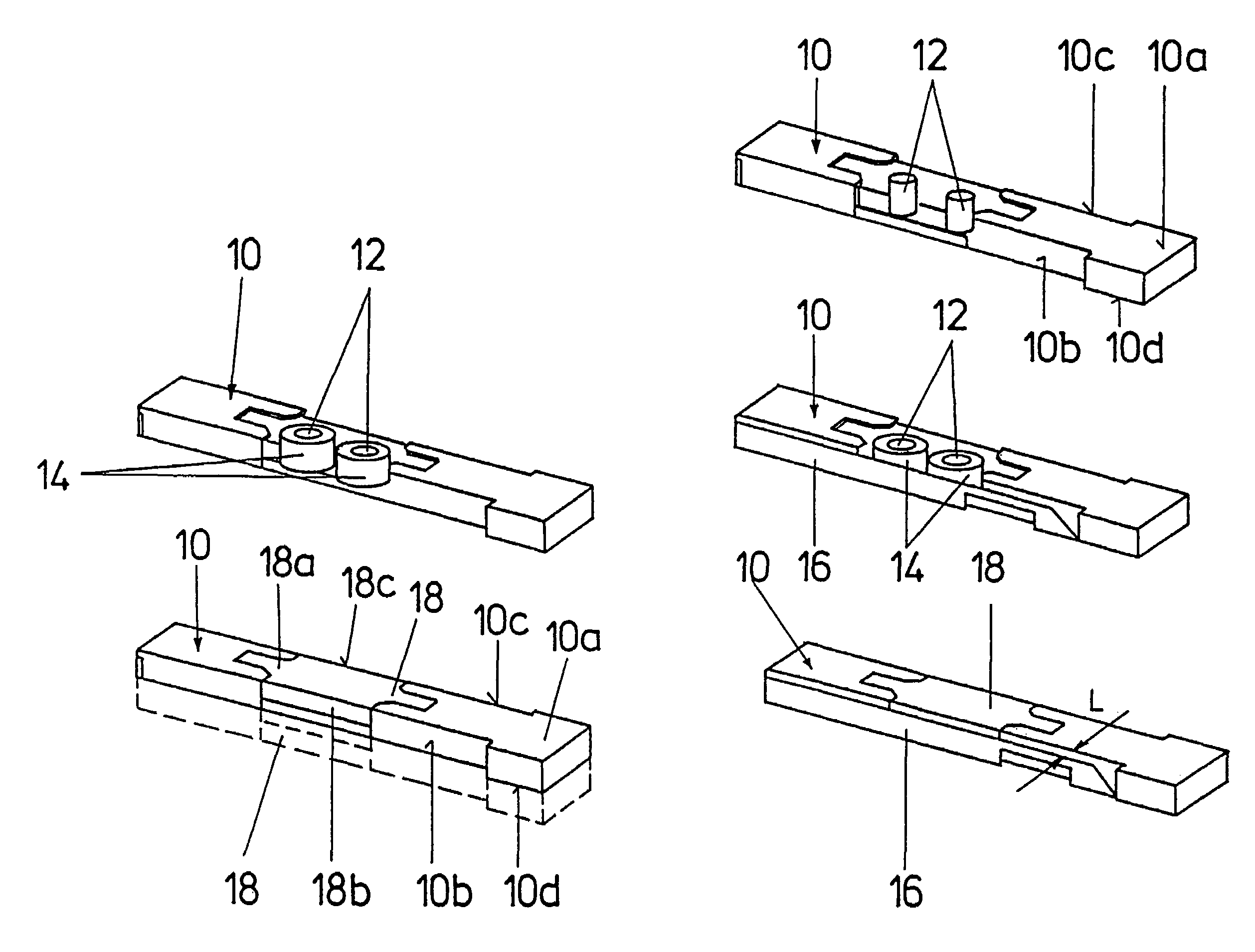
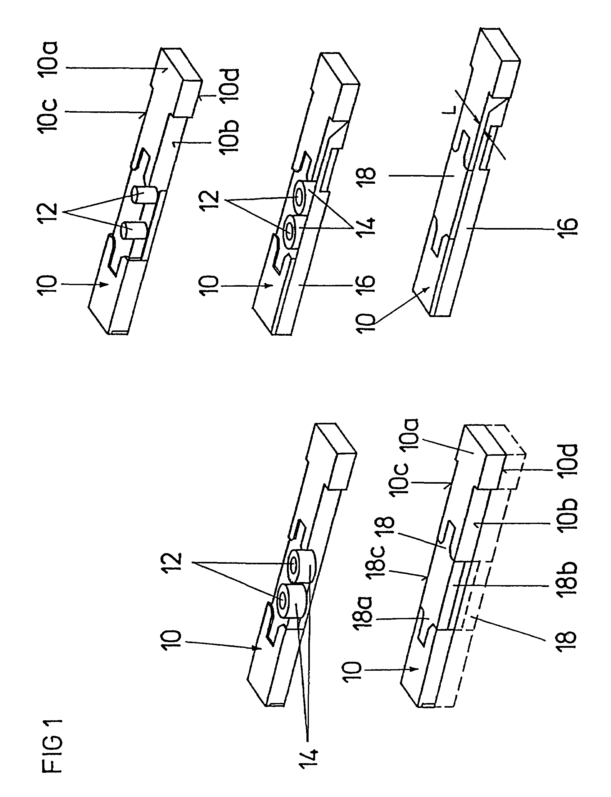
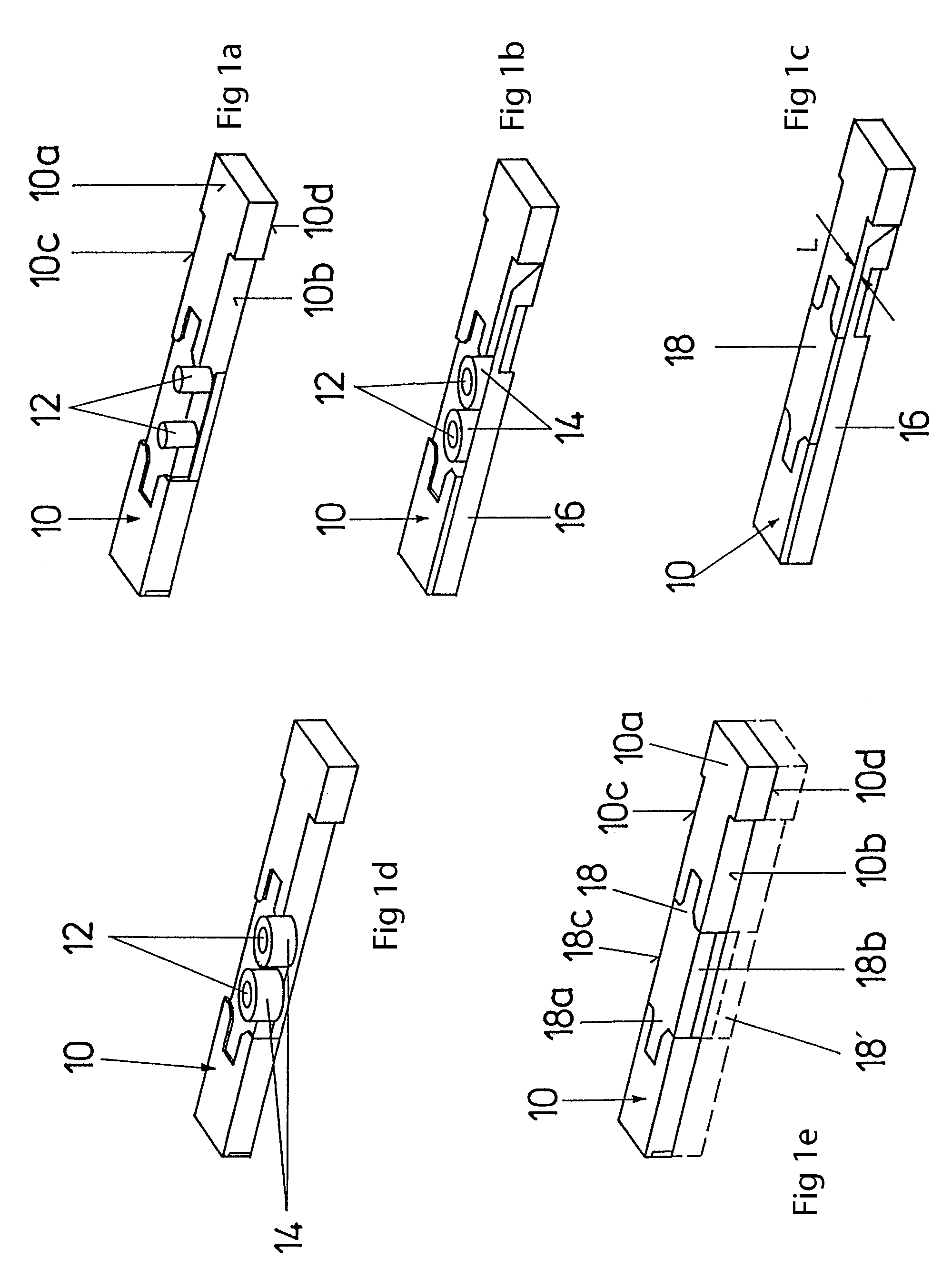
[0026]In the following figures, identical parts or parts having an identical function have identical reference numerals, unless otherwise indicated.

[0027]FIGS. 1a–1e show different perspective views of an upper section of a guide rod 10. An electromagnet system is integrated in the upper section of the guide rod 10. The electromagnet system of the conventional guide rod 10 according to FIG. 1a has two support members in the form of iron cores 12 which are spaced apart along the longitudinal axis of the guide rod 10 and have a circular cross section. As seen in FIGS. 1b and 1d, respective excitation coils 14 are wound around each of the iron cores. The two excitation coils 14 which may each have 1400 turns, are connected in series and connected to a current source through wires (not shown). The iron cores 12 and the excitation coils 14 wound on the iron cores 12 are disposed in a cavity of the guide rod 10, i.e., between the two top surfaces 10a and 10d and the two opposing side wall...


PUM


Abstract

A guide rod assembly for a Jacquard loom is described which is narrower (10 mm or less), instead of 13 mm of conventional guide rods. This reduction in width is attained reducing the overall height of the magnet system integrated in the guide rod. The magnet system has a support member in the form of an iron core with an elongated or oval cross-section, with an excitation coil wound around the iron core. Pole strips are in contact with both front faces of the iron core. The respective top surfaces of the pole strips are spaced apart by less than 13 mm.

Description

FIELD OF THE INVENTION[0001]The invention relates to a guide rod for a Jacquard loom, in particular a guide rod with an electromagnet system integrated in the guide rod.BACKGROUND OF THE INVENTION[0002]Such guide rods, also called selectors, are employed in large numbers in Jacquard looms. The guide rods are arranged side-by-side and stacked on top of each other, as described, for example, in G 9112552.9, EP 0494044 A1 and SK 277761.[0003]Jacquard looms are shed-forming devices for weaving woven fabrics having large patterns. The Jacquard loom raises and lowers each warp end individually, so that woven items with a practically unlimited variety of patterns can be produced.[0004]Conventional Jacquard looms use electronic modules with electromagnets to controllably raise and lower the individual warp threads. Blades are provided to raise and lower so-called lamellae or collar boards disposed on the guide rods. Hooks are suspended from the collar boards. Harness cords are suspended fro...

Claims


Application Information

Patent Timeline
Patent Type & Authority Patents(United States)
IPC IPC(8): D03C3/00D03C3/20
CPCD03C3/20
Inventor IRMER, NORBERTWAHL, PETER
Owner N V MICHEL VAN DE WIELE
Why Eureka
Try Eureka