
Process for producing a fibrous structure having increased surface area

a fibrous structure and surface area technology, applied in the direction of non-fibrous pulp addition, photomechanical equipment, instruments, etc., can solve the problems of affecting the strength of paper, reducing the area of the web comprising the relatively low-density network area that imparts,

Inactive Publication Date: 2006-10-10
THE PROCTER & GAMBLE COMPANY
View PDF76 Cites 58 Cited by
  • Summary
  • Abstract
  • Description
  • Claims
  • Application Information

AI Technical Summary

Benefits of technology

"The present invention provides a process for making a fibrous structure by using a deflection member with a patterned framework. The fibrous structure is formed by placing fibers on the deflection member and then separating it from the fibrous structure. The fibrous structure has void spaces between the patterned framework and suspended portions. The technical effect of this process is that it allows for the creation of a fibrous structure with improved strength and flexibility."

Problems solved by technology

However, increasing the web's surface area by increasing the area comprising the relatively low-density pillows would result in decreasing the web's area comprising the relatively low-density network area that imparts the strength.
That is, increasing a ratio of the area comprising pillows relative to the area comprising the network would negatively affect the strength of the paper, because the pillows have a relatively low intrinsic strength of the paper, because the pillows have a relatively low desirable to minimize the trade-off between the surface area of the high-density network region primarily providing strength, and the surface area of the low-density region primarily providing softness and absorbency.

Method used


Image

  • Process for producing a fibrous structure having increased surface area
  • Process for producing a fibrous structure having increased surface area
  • Process for producing a fibrous structure having increased surface area

Examples


example

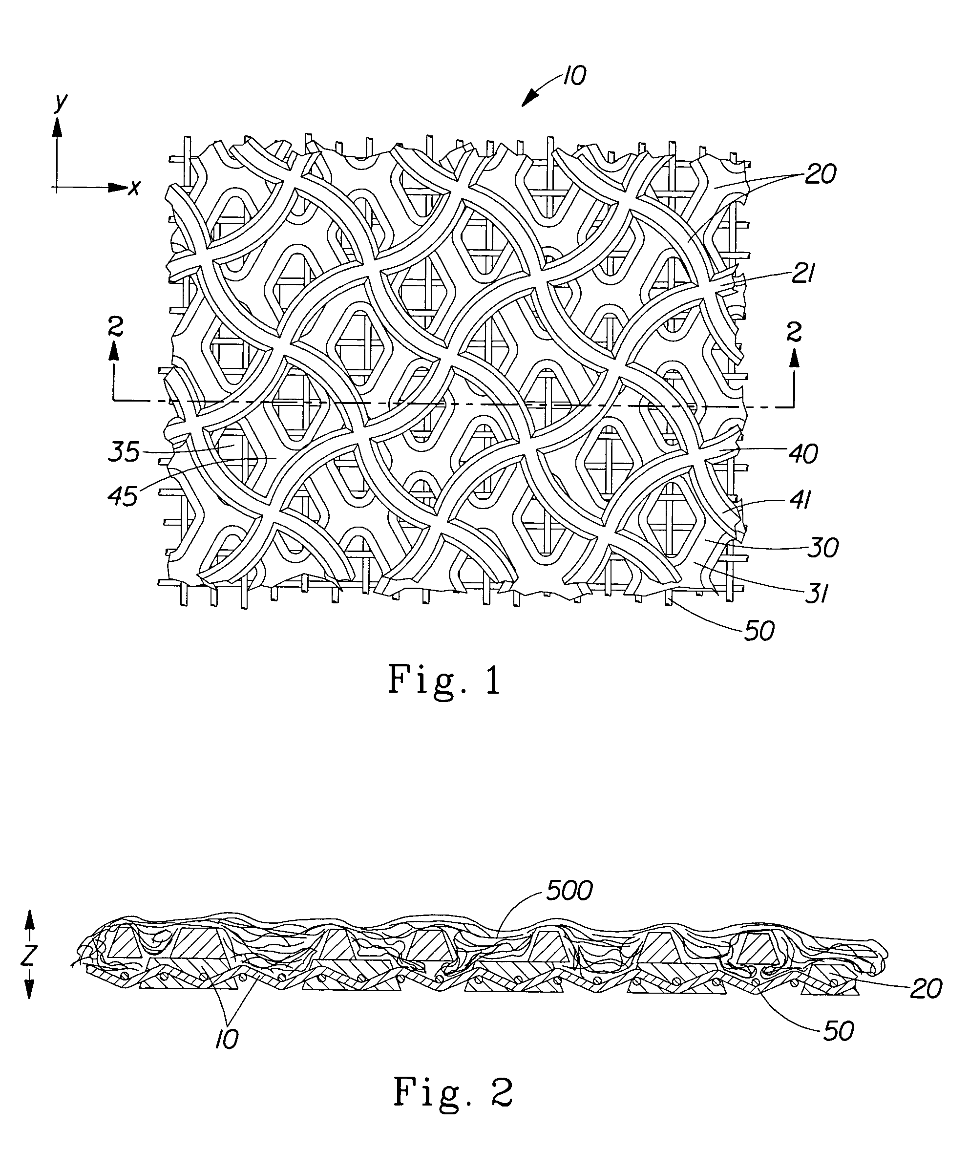
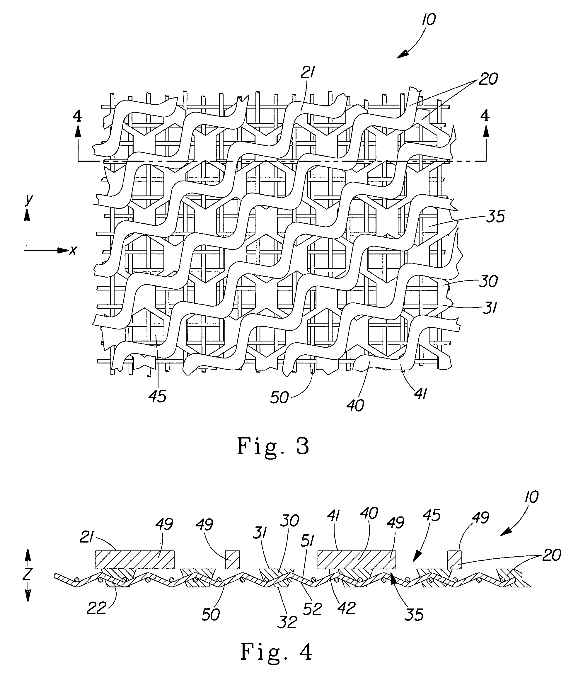
[0189]The deflection member 10 of the present invention was produced with a first layer 30 comprising nine discrete deflection conduits per square inch, and a second layer 40 comprising forty-one deflection conduits per square inch (“41 / 9” pattern). The conduits' geometry was a diamond with filleted vertices. The cumulative projected open area (ΣR) of the deflection conduits 35 of the first layer 30 was 0.0756 square inches, and the cumulative projected open area of the second layer's deflection conduits was 0.0161 square inches. The first and second specific resulting open areas R1 and R2 (i.e., ratios of the cumulative projected open area of a given layer to a given surface area) was computed to be: R1=68% for the first layer, and R2=66% for the second layer. The thickness of each layer was 0.020 inches. The two-layer structure was bonded to a dual-layer 48×55 mesh belt known commercially as a stacked, warped, dual-layer belt, which is produced by the Appleton Wire Division of Alb...


PUM

PropertyMeasurementUnit
surface areaaaaaaaaaaa
areaaaaaaaaaaa

Abstract

A process for making a fibrous structure including the steps of: providing a deflection member comprising a macroscopically monoplanar, patterned framework having a backside forming an X-Y plane and a web-side opposite to the backside, wherein the framework comprises a plurality of bases extending from the X-Y plane in a Z-direction perpendicular to the X-Y plane, and a plurality of suspended portions laterally extending from the plurality of bases in at least one direction substantially parallel to the X-Y plane and elevated in the Z-direction from the X-Y plane to form void spaces between the X-Y plane and the suspended portions; providing a plurality of fibers on the deflection member, thereby forming a partly-formed fibrous structure; and separating the partly-formed fibrous structure from the deflection member, thereby forming the fibrous structure.

Description

CROSS REFERENCE TO RELATED APPLICATIONS[0001]This application is a divisional application of U.S. application Ser. No. 09 / 695,117 filed Oct. 24, 2000, now U.S. Pat. No. 6,660,129.FIELD OF THE INVENTION[0002]The present invention is related to processes for making strong, soft, absorbent fibrous webs, such as, for example, paper webs. More particularly, this invention is concerned with structured fibrous webs, equipment used to make such structured fibrous webs, and processes therefor.BACKGROUND OF THE INVENTION[0003]Products made from a fibrous web are used for a variety of purposes. For example, paper towels, facial tissues, toilet tissues, napkins, and the like are in constant use in modern industrialized societies. The large demand for such paper products has created a demand for improved versions of the products. If the paper products such as paper towels, facial tissues, napkins, toilet tissues, mop heads, and the like are to perform their intended tasks and to find wide accept...

Claims


Application Information

Patent Timeline
Patent Type & Authority Patents(United States)
IPC IPC(8): D21F11/00G03F7/12
CPCD21F11/006G03F7/12Y10T428/24612Y10T428/24479
Inventor CABELL, DAVID WILLIAMTROKHAN, PAUL DENNIS
Owner THE PROCTER & GAMBLE COMPANY
Learn More