Flat type image display device

a display device and flat-type technology, applied in the direction of television systems, electrical apparatus casings/cabinets/drawers, instruments, etc., can solve the problems of increasing the number of parts, reducing the service life of the device, and bare sub-conductor and conductive components,

Inactive Publication Date: 2006-10-10
SONY CORP
View PDF12 Cites 24 Cited by
  • Summary
  • Abstract
  • Description
  • Claims
  • Application Information

AI Technical Summary

Problems solved by technology

In the case where a substrate for wiring and a conductive member are disposed on the rear surface side of a bracket, however, these substrate and conductive member are bare.
In this case, although it is also possible to provide a cover for covering the substrate and conductive member, the number of parts is increased by the amount to provide the cover, thus increasing the cost.

Method used


Image

  • Flat type image display device
  • Flat type image display device
  • Flat type image display device

Examples


Embodiment Construction

[0026]With reference to the accompanying drawings, the details of a flat type image display apparatus of the present invention will be described hereinafter. Note that the following preferred embodiment is one that is applied to a flat type image display apparatus wherein a plasma display panel is used as a screen.

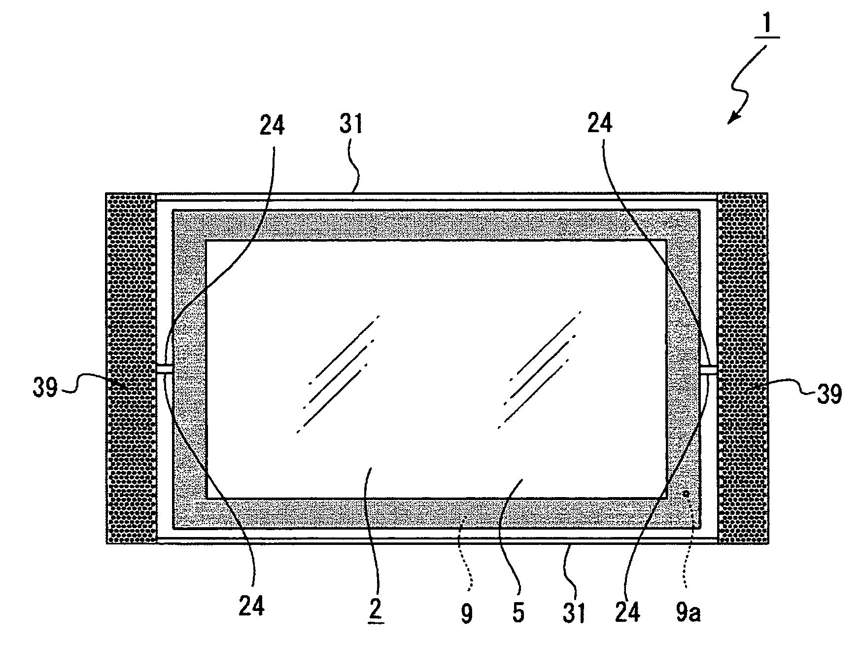
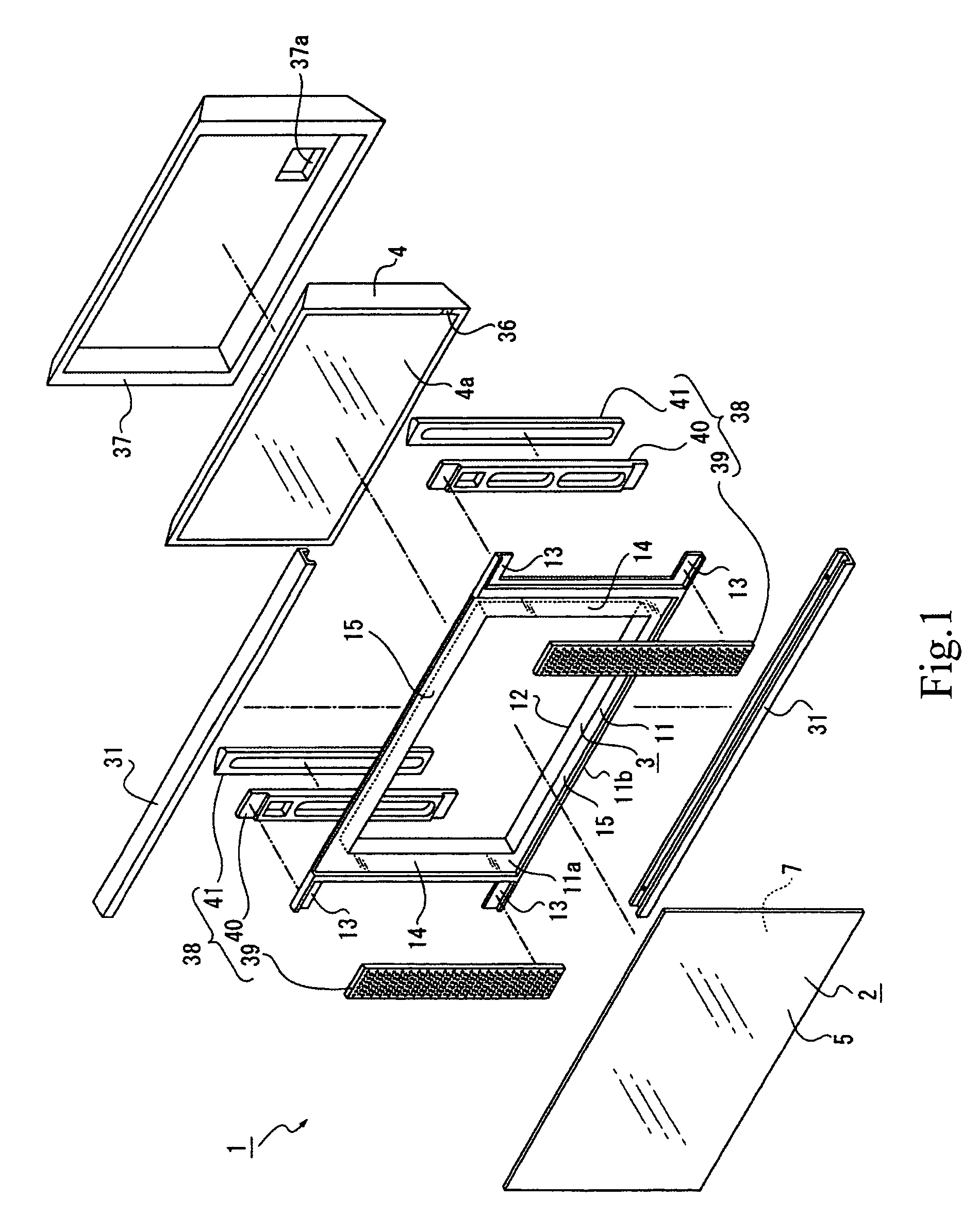
[0027]A flat type image display apparatus 1 is provided with a front panel 2, a bracket 3 and an apparatus body section 4 (see FIG. 1).

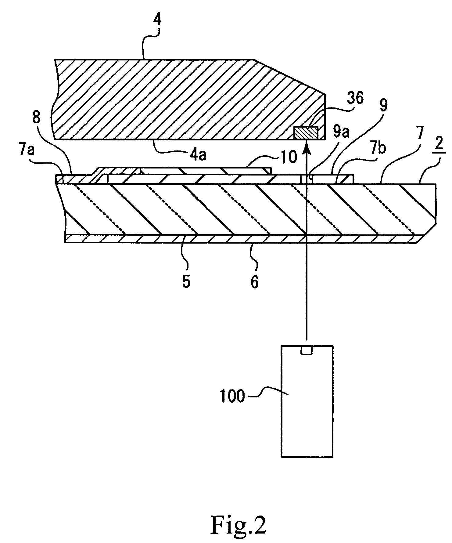
[0028]The front panel 2 is formed in a landscape oriented rectangle and formed by a transparent material such as glass, polycarbonate, acryl or the like. An anti-reflective film 6 for preventing reflection of external light is attached to the entire surface of a front surface 5 of the front panel 2 (see FIG. 2).

[0029]A rear surface 7 of the front panel 2 is constructed by an attached portion 7a and a non-attached portion 7b, and the area of the rear surface 7 except for its outer peripheral portion is defined as the attached portion 7a and ...


PUM


Abstract

There are provided a bracket 3 that has a frame section 11 integrally formed by a transparent material, an apparatus mounting section 12 disposed in an inner peripheral edge of the frame section, and parts fixing sections 13, 13, . . . disposed on the outside of the frame section; a front panel 2 that is formed by a transparent material and disposed on the front surface side of the bracket; an apparatus body section 4 that has a screen surface 4a and is mounted at the apparatus mounting section of the bracket; holding members 31, 31 that hold the front panel and the bracket in the state that they are connected together at the front and rear; and functional sections that are fixed to the parts fixing sections of the bracket so as to be disposed on the outside of the front panel, and that sends and receives electric signals to exhibit a predetermined function. Signal paths 35, 35 to perform sending and receiving of electric signals between the apparatus body section and the functional sections are formed in the inside of the bracket or in a boundary portion between the front panel and the bracket. This enables sending and receiving of electric signals between the apparatus body section and the functional sections that send and receive electric signals to exhibit a predetermined function, while maintaining good design quality.

Description

TECHNICAL FIELD[0001]The present invention relates to a flat type image display apparatus. Specifically, the invention relates to a technical field that enables to send and receive electric signals between an apparatus body section and a functional section that sends and receives electric signals and exhibits a predetermined function, while maintaining good design quality.BACKGROUND ART[0002]As a flat type image display apparatus displaying images on a screen, there is, for example, one that uses as a screen a plasma display panel (PDP) or the like.[0003]In flat type image display apparatuses, the type that disposes a screen so as to be surrounded by a frame section called bezel has been widely used. However, there is estimated the spread of flat type image display apparatuses of various type seeking for a higher design quality, in order to meet the request of recent market.[0004]As an example of flat type image display apparatuses seeking for a higher design quality, there is being...

Claims


Application Information

Patent Timeline
Patent Type & Authority Patents(United States)
IPC IPC(8): G06F1/16H05K5/00H05K7/00
CPCG06F1/1601H04N5/64H04N5/645Y10S345/905
Inventor TAKAHASHI, HITOSHIMAEDA, HIROYOSHINOGUCHI, MASAMOTOONO, HIROYUKINIITSU, TAKUYASAKATA, TATSUYATAKAGI, KEIICHIKATAYAMA, KENICHI
Owner SONY CORP
Why Eureka
Try Eureka