
Serial bone plate design method based on average thighbone model

A design method and bone plate technology, applied in calculation, special data processing applications, instruments, etc., can solve the problems of reducing postoperative effect, increasing patient pain, increasing corrosion and electrolytic potential, etc., to improve design efficiency and improve operation efficiency. quality effect

Active Publication Date: 2015-09-23
HOHAI UNIV CHANGZHOU
View PDF5 Cites 21 Cited by
  • Summary
  • Abstract
  • Description
  • Claims
  • Application Information

AI Technical Summary

Problems solved by technology

However, the experimental results show that the morphological parameters of the femur vary greatly among different races. The serialized bone plate designed according to the morphological parameters of the Westerner’s femur forces orthopedic surgeons to constantly compare and shape the bone plate (bending, cutting, etc.) during clinical operations. , not only poor matching, which reduces the postoperative effect, but also increases the pain level of the patient
In addition, the material and structural characteristics of the bone plate itself indicate that cold shaping will change the internal structure of the material and reduce the material performance. Scratching on the surface of the bone plate will also greatly increase the effects of corrosion and electrolytic potential, shortening the fatigue life of the bone plate
All of the above will lead to a high incidence of malunion, nonunion and infection after femoral surgery, and even cause serious immune system damage, malnutrition, lung and gastrointestinal dysfunction and nervous system damage
At the same time, the surface of the femur appears as a complex curved surface. The effective definition of femoral parameters and the division of bone plate models undoubtedly add challenges to the serial design of bone plates

Method used


Image

  • Serial bone plate design method based on average thighbone model
  • Serial bone plate design method based on average thighbone model
  • Serial bone plate design method based on average thighbone model

Examples


Embodiment Construction

[0032] The present invention will be specifically introduced below in conjunction with the accompanying drawings and specific embodiments.

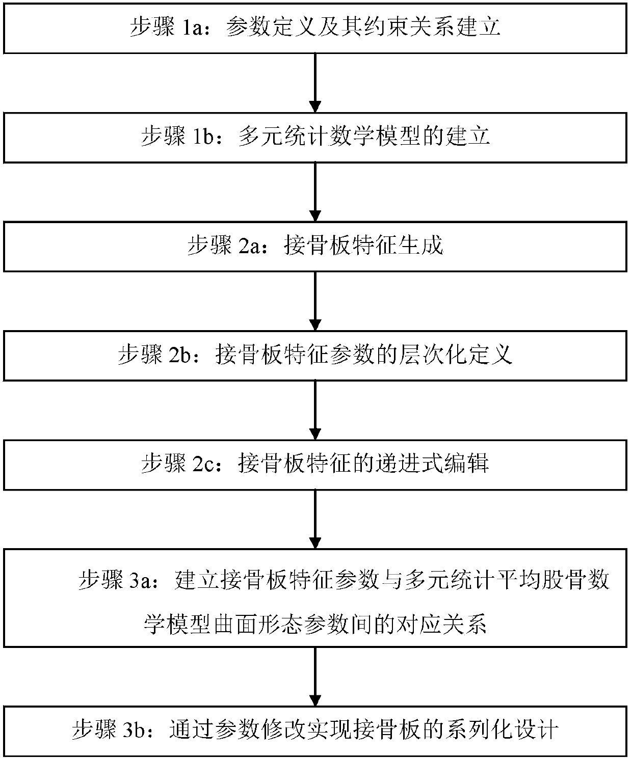
[0033] refer to figure 1 As shown, a serial design method of bone plate based on the average femoral model includes the following steps:

[0034] Step 1: Construction of average femur model

[0035] Step 1a: Parameter definition and establishment of constraint relationship. Define parameters (including main morphological parameters and detailed parameters) for the femoral surface model according to medical significance, and establish the correlation between each parameter.

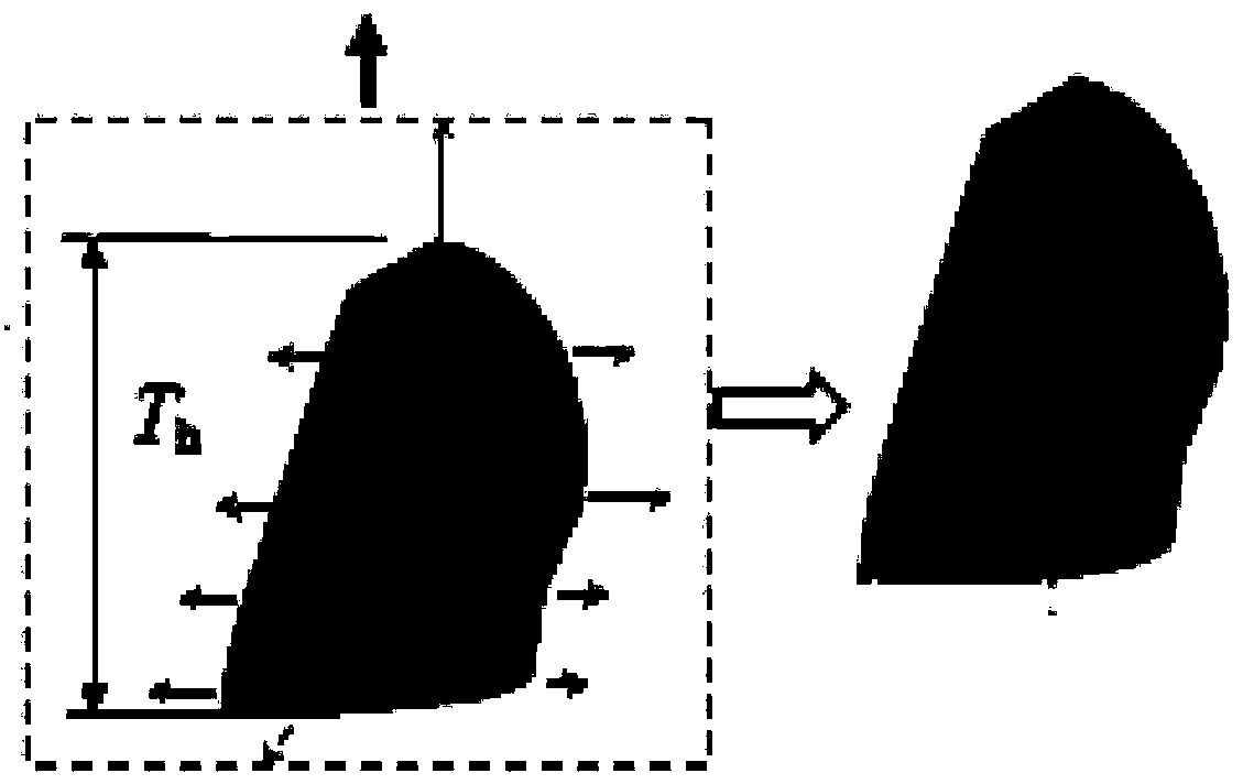
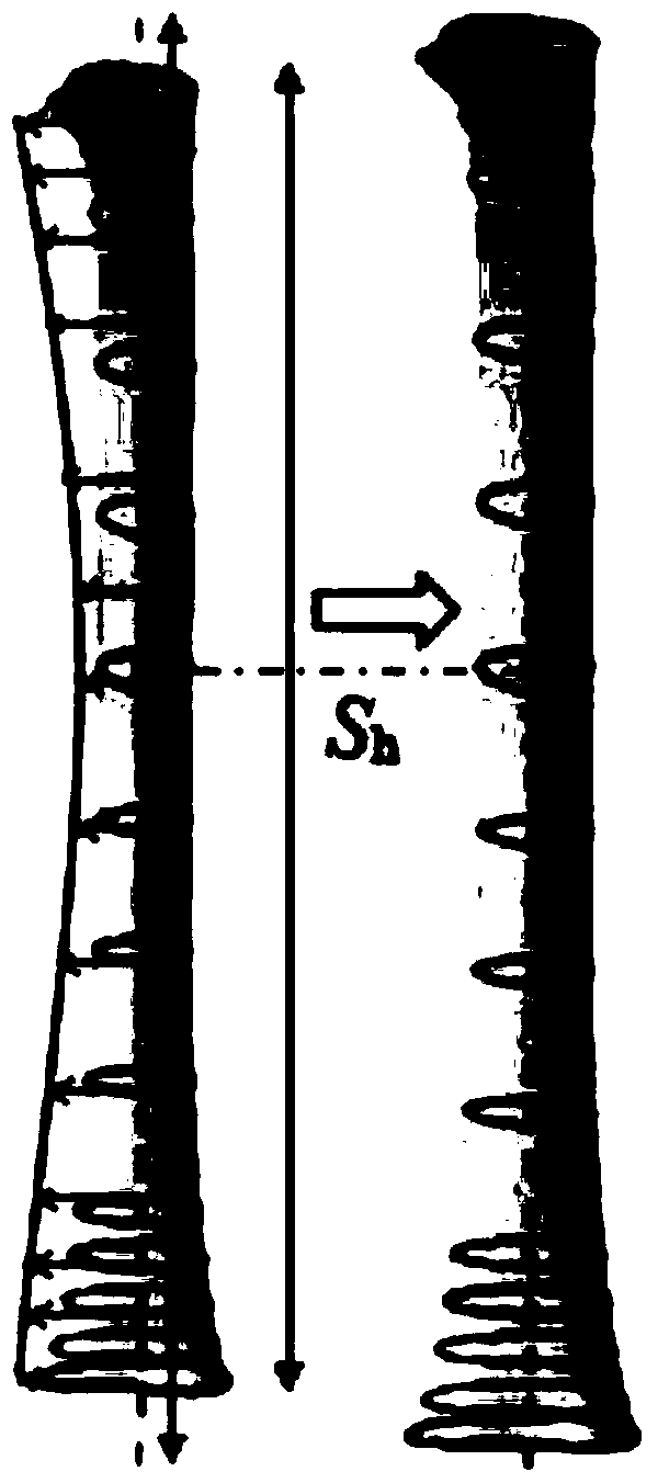
[0036] The main morphological parameters are parameters reflecting the local shape of the femoral surface, including characteristic parameters of the femoral head, neck, trochanter, femoral shaft, and condyle.

[0037] The detailed parameters are mainly the parameters included in the characteristic parameters of the femoral head that specifically reflect an obvious...


PUM


Abstract

The invention discloses a serial bone plate design method based on an average thighbone model. The design method includes the steps of 1 building the average thighbone model, wherein parameters are defined, a constraint relation of the parameters is set up, and a multivariate statistics mathematic model is set up; 2 parameterizing characteristics of a bone plate, wherein the characteristics of the bone plate are generated, the characteristic parameters of the bone plate are defined in a layered mode, and the characteristics of the bone plate are compiled progressively; 3 designing the bone plate serially, wherein a mapping relation between the characteristic parameters of the bone plate and curved surface morphological parameters of the average thighbone model is set up, and serial bone plate design is achieved by modifying the parameters. A scientific basis is provided for reasonable and serial bone plate design in the field of computer-assisted orthopedic operations, and the serial bone plate design method is of great significance in improving the bone plate design quality and shortening design time.

Description

technical field [0001] The invention relates to a digital orthopedics technology, in particular to a serial design method of a bone plate based on an average femur model, and belongs to the field of computer-aided design. Background technique [0002] As the longest tubular bone in the human body, the femur bears all the weight of the upper body of the human body, and femoral lesions and fractures occur frequently. The wide application of computer digital technology in clinical orthopedics has promoted the rapid development of new digital orthopedics, and opened up a new idea for clinical treatment of using bone plates to fix damaged femurs. Based on the knowledge and understanding of the similarity of the physiological structure characteristics of the human femur, domestic medical device manufacturers currently produce a series of bone plates of different models to meet the needs of orthopedic clinical treatment of traumatic fractures. However, the experimental results sho...

Claims


Application Information

Patent Timeline
Patent Type & Authority Applications(China)
IPC IPC(8): G06F17/50
Inventor 王淋何坤金陈正鸣王波陈小中耿维忠
Owner HOHAI UNIV CHANGZHOU
Learn More