

Method for free curved surface optical component for collimating light shaping
A technology of optical components and design methods, applied in the directions of optical components, optics, lighting device components, etc., can solve problems such as discontinuous free-form surfaces, difficult problems, and not satisfying integrable conditions.
- Summary
- Abstract
- Description
- Claims
- Application Information
AI Technical Summary
Problems solved by technology
Method used
Image

Examples
Embodiment 1
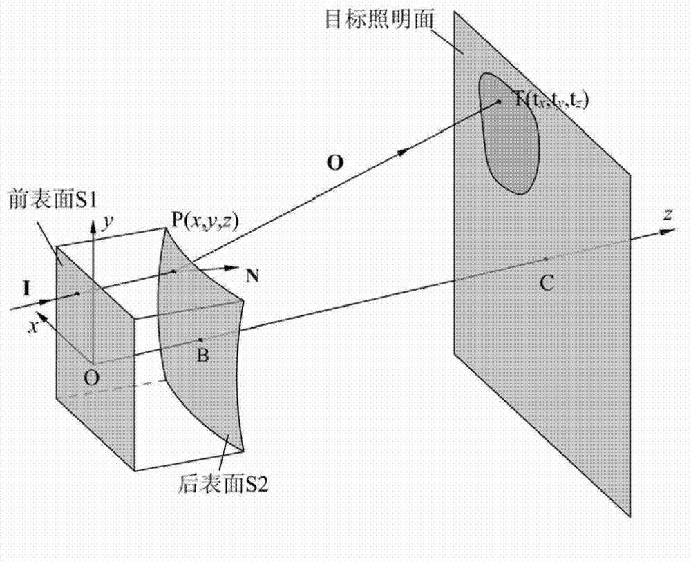
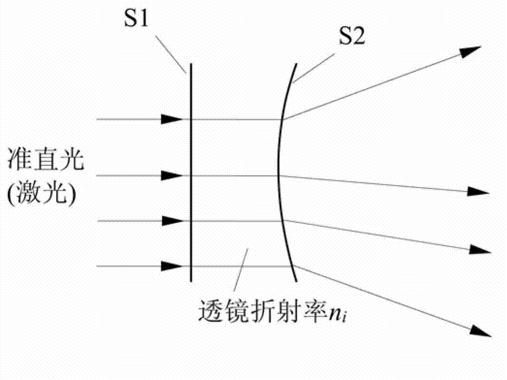
[0058] Embodiment 1: The free-form surface optical element intends to adopt such as attached image 3 In the type of structure shown, the front surface S1 adopts a plane, and the rear surface S2 is a free-form surface, so the focus of this design is how to design the rear surface S2 of this free-form optical element. Assuming that the incident collimated light beam has an equal intensity distribution, the light beam will produce a square illumination with a smiling face pattern on the target illumination surface after light distribution by the free-form surface lens. It is required that both the smiling face pattern and the square background are uniformly illuminated, and the illuminance ratio of the two is 3:2. The z coordinate of the vertex of the free-form surface S2 on the back surface is 5 mm, the distance between the front surface S1 of the free-form lens and the target lighting surface is 300 mm, the side length of the square illumination spot is 100 mm, and the cross-s...
Embodiment 2
[0080] Embodiment 2: The free-form surface optical element intends to adopt such as attached image 3 In the type of structure shown, the front surface S1 adopts a plane, and the rear surface S2 is a free-form surface, so the focus of this design is how to design the rear surface S2 of this free-form optical element. Assuming that the incident collimated light beam has an equal intensity distribution, the light beam will produce a rectangular illumination with the word "mao" on the target illumination surface after light distribution by the free-form surface lens. It is required that both the smiling face pattern and the rectangular background are uniformly illuminated, and the illuminance ratio of the two is 3:2. The z coordinate of the vertex of the free-form surface S2 on the rear surface is 5mm, the distance between the front surface S1 of the free-form lens and the target lighting surface is 300mm, the length and width of the rectangular illumination spot are 100mm and 50mm...
PUM
 Abstract
Description
Claims
Application Information