Method for designing coating uniformity correction mask for spherical optical elements on planetary rotating jigs of vacuum coating machines

A technology of vacuum coating machine and correcting baffles, which is applied in vacuum evaporation coating, sputtering coating, ion implantation coating, etc., and can solve the problems that the mathematical expression of correcting baffles cannot be directly obtained, and it takes a long time

Active Publication Date: 2012-10-17
INST OF OPTICS & ELECTRONICS - CHINESE ACAD OF SCI
View PDF10 Cites 31 Cited by
  • Summary
  • Abstract
  • Description
  • Claims
  • Application Information

AI Technical Summary

Problems solved by technology

This modified baffle design process takes a long time, usually requires several or even more than ten experiments to obtain satisfactory results, and requires experienced designers
The method of using theory-aided design to correct the baffle has not been applied to the planetary rotation fixture, mainly because in the planetary rotation fixture, the optical element always rotates at high speed, and the position of the point on the mirror surface has no fixed relationship with the position of the correction baffle. Therefore, the mathematical expression for the modified baffle shape cannot be directly obtained

Method used


Image

  • Method for designing coating uniformity correction mask for spherical optical elements on planetary rotating jigs of vacuum coating machines
  • Method for designing coating uniformity correction mask for spherical optical elements on planetary rotating jigs of vacuum coating machines
  • Method for designing coating uniformity correction mask for spherical optical elements on planetary rotating jigs of vacuum coating machines

Examples


Embodiment Construction

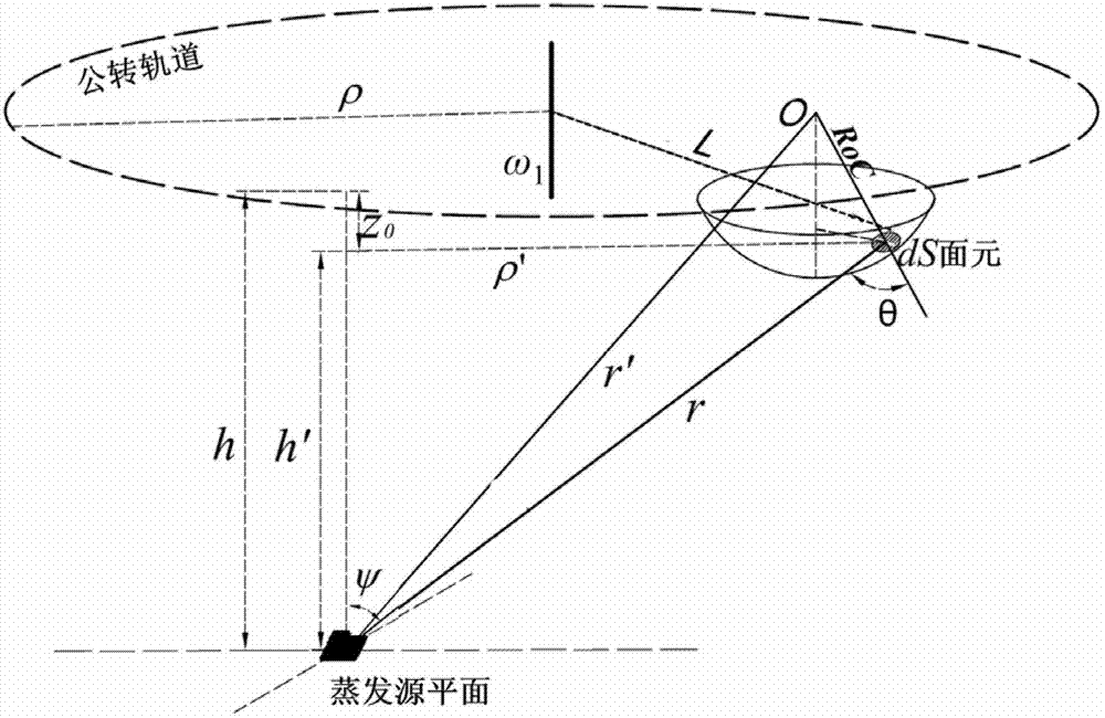
[0033] attached figure 1 is a schematic diagram of the coating process of spherical optical elements on the planetary rotating fixture of the vacuum coating machine, where r represents the vector from the evaporation source to the deposition position (dS bin) length θ is The angle between and the surface normal of the optical element, ψ is The included angle with the normal of the source plane, r' is the distance between the center of the sphere where the convex or concave sphere is located and the evaporation source, h' and ρ' are the vertical and horizontal distances from the evaporation source to the panel dS, respectively , ρ is the orbital radius of the planetary rotating jig, h is the distance between the orbital plane of the planetary rotating jig and the plane of the evaporation source. The center of the sphere where the spherical surface of the optical element is located is marked by O, and the radius of curvature of the sphere is RoC. The position of the sur...


PUM


Abstract

The invention discloses a method for designing a coating uniformity correction mask for spherical optical elements on planetary rotating jigs of vacuum coating machines, which is used for studying the film thickness distribution of a plane or spherical optical element (subjected to coating) on a planetary rotating jig through establishing a coating model in a vacuum environment. Through enabling an optical element coating process in a planetary rotating jig to be equivalent to a coating process in a simple rotating jig, the initial shape of the coating uniformity correction mask in the planetary rotating jig is designed. Through optimizing the arc length magnification factor of the correction mask by using a computer until the film thickness uniformity reaches the optimal result, the actual shape of the coating uniformity correction mask for the spherical optical elements is obtained. According to the invention, the control on the film thickness uniformity of the spherical optical element with a large caliber and a large caliber / curvature radius ratio can be realized, thereby obtaining the uniformity of multilayer-film spectral characteristics of the spherical optical element with a large caliber and a large caliber / curvature radius ratio.

Description

technical field [0001] The invention relates to the technical field of thin film preparation, in particular to a design method for a correction baffle used in a planetary rotating fixture of a vacuum coating machine to control the uniformity of the film thickness of a spherical optical element. Background technique [0002] Optical thin films are an important part of modern optical systems. On the surface of almost all optical components, the preparation of thin films with special properties by physical or chemical methods has become a necessary means to improve the optical properties of optical components. With the development of high-precision optical measuring instruments, high-resolution optical imaging technology and lithography technology, the aperture of optical elements and the ratio of aperture / radius of curvature of spherical optical elements are getting larger and larger. In order to ensure the use of large aperture, large aperture / radius of curvature ratio The op...

Claims


Application Information

Patent Timeline
Patent Type & Authority Applications(China)
IPC IPC(8): C23C14/24
Inventor 柳存定李斌成孔明东郭春
Owner INST OF OPTICS & ELECTRONICS - CHINESE ACAD OF SCI
Why Eureka
Try Eureka