Systems and methods for providing forward mapping with visibility for and resolution of accumulated samples

a system and method technology, applied in the field of systems and methods for rendering images, can solve the problems of ineffective antialiasing of images, inability to achieve true anisotropic filtering, and high cost of the present architecture to achieve true anisotropic filtering, and achieve high frequency content and high quality results

Inactive Publication Date: 2006-10-10
MICROSOFT TECH LICENSING LLC
View PDF7 Cites 21 Cited by
  • Summary
  • Abstract
  • Description
  • Claims
  • Application Information

AI Technical Summary

Benefits of technology

[0025]In view of the foregoing, the present invention provides systems and methods for forward mapping, which accumulate and resolve over all samples forward mapped to each pixel bin. The invention uses a pixel, or sub-pixel, binning approach that accumulates and resolves over all samples, and performs particularly well compared to prior architectures in areas that have higher frequency content, solving the minification antialiasing problem and producing a high quality result. A filter determines the value(s) to assign to each pixel based upon accumulation and resolution, e.g., taking the mean, taking the median, taking the mode, taking the minimum, taking the maximum, applying a least squares fit or applying some other function, of all of the sample points that fall within the pixel bin(s), rather than assigning a value by selecting only the point sample that corresponds to the center of the pixel. During accumulation and resolution of each of the samples, since a point sample from a forefront object and a point sample from an occluded object may be received by the same bin, wherein only the former should be accumulated and resolved according to the accumulation and resolution process, a Z-range, or Z-interval, is assigned to each sample instead of the conventional Z-value. The Z-range is a function of the Z-value. Analysis of the overlapping of these Z-ranges then determines which samples are to be accumulated and resolved together according to the accumulation and resolution process, and which are not.

Problems solved by technology

Thus, the current rasterization architecture only samples at pixel centers, which is not an effective way to antialias images in all cases.
Without increasing the image size, using smaller triangles fails to achieve antialiasing because most of these small triangles do not cover a pixel center and, as a result, are totally ignored by the current rasterization architecture.
The current architecture works reasonably well when the texture map contains all the frequency information, because the texture can be represented as a pre-computed MIP-Map; however, true anisotropic filtering is very costly for the present architecture to achieve.
Forward mapping, however, can result in holes in an image that undergoes transformation, e.g., image warping, perspective transformation, etc., because some pixels in the destination image are not “filled in” by any locations from the source image, and are effectively left blank by the mapping.
Generally speaking, the severity of space left empty by such a forward mapping process can increase with the complexity or severity of change introduced by a transformation.
Current forward mapping approaches employ complex schemes to avoid the above-described undersampling that leaves gaps, or holes, between mapped samples where the source signal is magnified, but such complex approaches are presently inadequate for a variety of reasons.
Attempts to employ source-based sampling for 3-D surface rendering have been made, and research papers have proposed some source-based sampling schemes, but these attempts and schemes have not achieved any commercial success.
For volume rendering, extremely simple forward mapping algorithms can be used, but these algorithms disadvantageously have large destination footprints.
These methods, however, are very complex and introduce computational overhead in terms of both computing time and other resources like memory bandwidth.
In this regard, one problem with present techniques is that they do not target applications that combine conventional graphics with IBR and video.
Memory access remains a central problem, and an architecture tuned to IBR alone and ignoring 3-D graphics is insufficient.
A drawback of such an approach is that to sample content at the resolution of the display device inherently assumes that a single sampling rate is appropriate for all portions of the image.
Such a source sampling is typically not convenient to obtain, however, requiring special-purpose image resampling.
Additionally, evaluating this metric at numerous source samples is impractical.
Unfortunately, for 3-D graphics and even for perspectively transformed 2-D graphics, effective pre-filtering is difficult.
The standard MIP-Map pyramid approach constructs a 1-D sequence of increasingly decimated signal versions, but the decimation is isotropic and thus blurs too much, or alternatively, “leaks” aliasing, if one direction in the source signal is minified more than another.
As a result, inverse-mapping 3-D graphics hardware is moving toward anisotropic filtering of greater sophistication and extent of anisotropy handled, but at the expense of computational complexity.
Moreover, aliasing problems due to “minification”, where high frequency source content is compressed into a small region in the destination, has always been a problem for present techniques and thus there is a need for a technique that addresses the minification case in a superior manner.
In brief, while present rasterization architectures can effectively antialias signals represented as texture maps, it is due to such architectures' use of expensive backward mapping and on-the-fly trilinear and anisotropic filtering.

Method used


Image

  • Systems and methods for providing forward mapping with visibility for and resolution of accumulated samples
  • Systems and methods for providing forward mapping with visibility for and resolution of accumulated samples
  • Systems and methods for providing forward mapping with visibility for and resolution of accumulated samples

Examples


Embodiment Construction

Overview

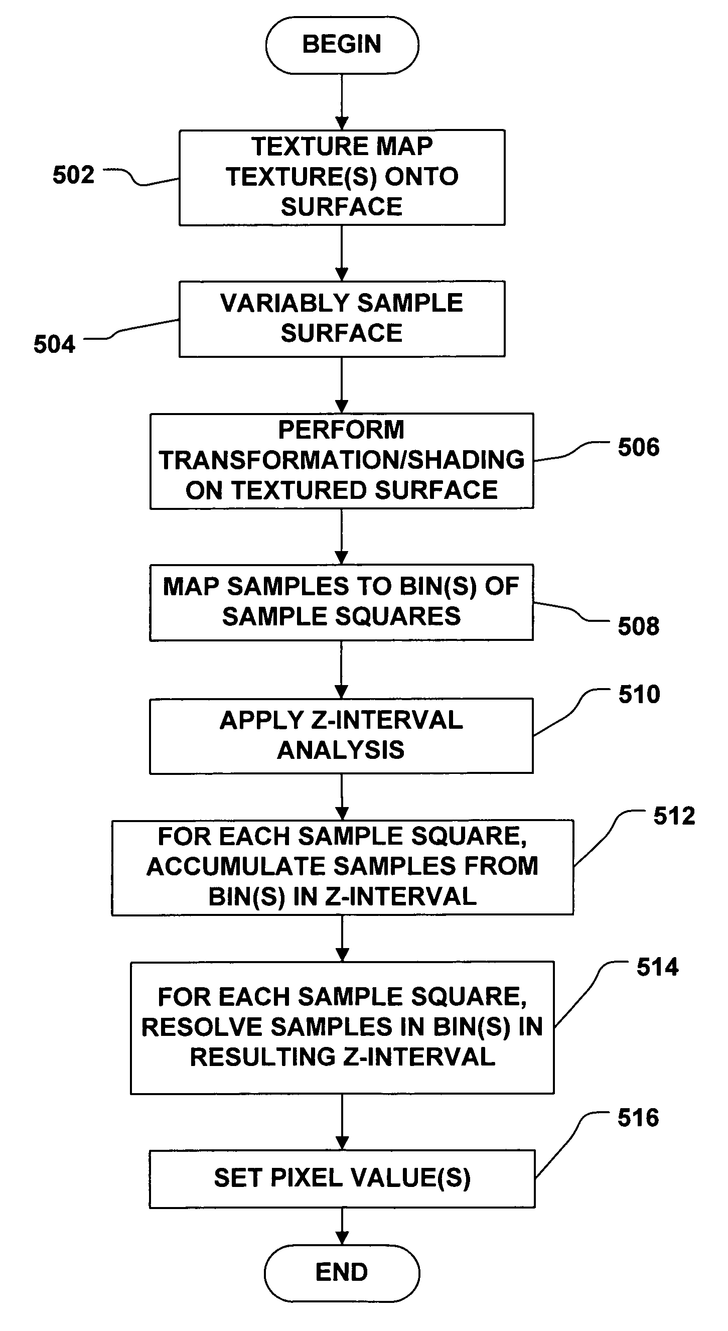
[0042]The invention thus provides methods and systems for providing forward mapping with resolution and visibility. In accordance with the invention, the surface, e.g., the textured geometry, to be rendered is sampled, or oversampled, at a variable rate that reflects variations in frequency among different regions, taking into account any transformation that will be applied to the surface prior to rendering and the view parameters of the rendering device, thus ensuring that each bin of rendering process includes at least a predetermined number of sample, e.g., at least one sample per bin. High frequency regions of the source, i.e., those regions having a finer level of detail, are sampled at a higher rate than low frequency regions of the source. In one embodiment, a tiling approach to division of the source(s) is proposed. A geometry map can be used to correlate texture samples with points on the surface. The methods of the invention can use a geometry map, but the methods ...


PUM


Abstract

Forward mapping is provided, which accumulates and resolves over all samples forward mapped to each pixel bin. During accumulation and resolution of each of the samples, since a point sample from a forefront object and a point sample from an occluded object may be received by the same bin, wherein only the former should be accumulated and resolved according to the accumulation and resolution process, a Z-range, or Z-interval, is assigned to each sample instead of the conventional Z-value. The Z-range is a function of the Z-value. Analysis of the overlapping of these Z-ranges then determines which samples are to be accumulated and resolved together according to the accumulation and resolution process, and which are not.

Description

FIELD OF THE INVENTION[0001]The present invention is directed to systems and methods for rendering images at a very high image quality. More particularly, the present invention relates to systems and methods for providing forward mapping with accumulation, resolution and visibility.BACKGROUND OF THE INVENTION[0002]Conventionally, as illustrated in FIG. 1A, complex three dimensional (3-D) objects, or portions thereof, can be represented by collections of adjacent triangles (“a mesh”) representing the approximate geometry of the 3-D object, or by a geometry map, or surface, in two dimensional (2-D) surface space. One or more texture maps can be mapped to the surface to create a textured surface according to a texture mapping process. In a conventional graphics system, the surface geometry sampling happens before texture sampling. In this regard, signals textured over a surface can be very general, and can specify any sort of intermediate result that can be input to a shader procedure ...

Claims


Application Information

Patent Timeline
Patent Type & Authority Patents(United States)
IPC IPC(8): G06K9/36G06T15/40G06T15/20
CPCG06T15/04G06T15/405
Inventor SNYDER, JOHN MICHAEL
Owner MICROSOFT TECH LICENSING LLC
Why Eureka
Try Eureka