Method and apparatus for supporting and clamping a substrate

a technology for supporting and stabilizing substrates, applied in the direction of coatings, printing, conductive pattern formation, etc., can solve the problems of preventing the lateral movement of the substrate in the x and y directions, and achieve the effect of preventing the z directional movement of the substra

Active Publication Date: 2006-10-17
SPEEDLINE TECH
View PDF12 Cites 30 Cited by
  • Summary
  • Abstract
  • Description
  • Claims
  • Application Information

AI Technical Summary

Problems solved by technology

One disadvantage associated with this approach is that the foils and the substrate support, while preventing up and down movement of the substrate in the z direction, fail to prevent lateral movement of the substrate in the x and y directions.

Method used


Image

  • Method and apparatus for supporting and clamping a substrate
  • Method and apparatus for supporting and clamping a substrate
  • Method and apparatus for supporting and clamping a substrate

Examples


Embodiment Construction

[0019]This invention is not limited in its application to the details of construction and the arrangement of components set forth in the following description or illustrated in the drawings. The invention is capable of other embodiments and of being practiced or of being carried out in various ways. Also, the phraseology and terminology used herein is for the purpose of description and should not be regarded as limiting. The use of “including,”“comprising,”“having,”“containing,”“involving,” and variations thereof herein, is meant to encompass the items listed thereafter and equivalents thereof as well as additional items.

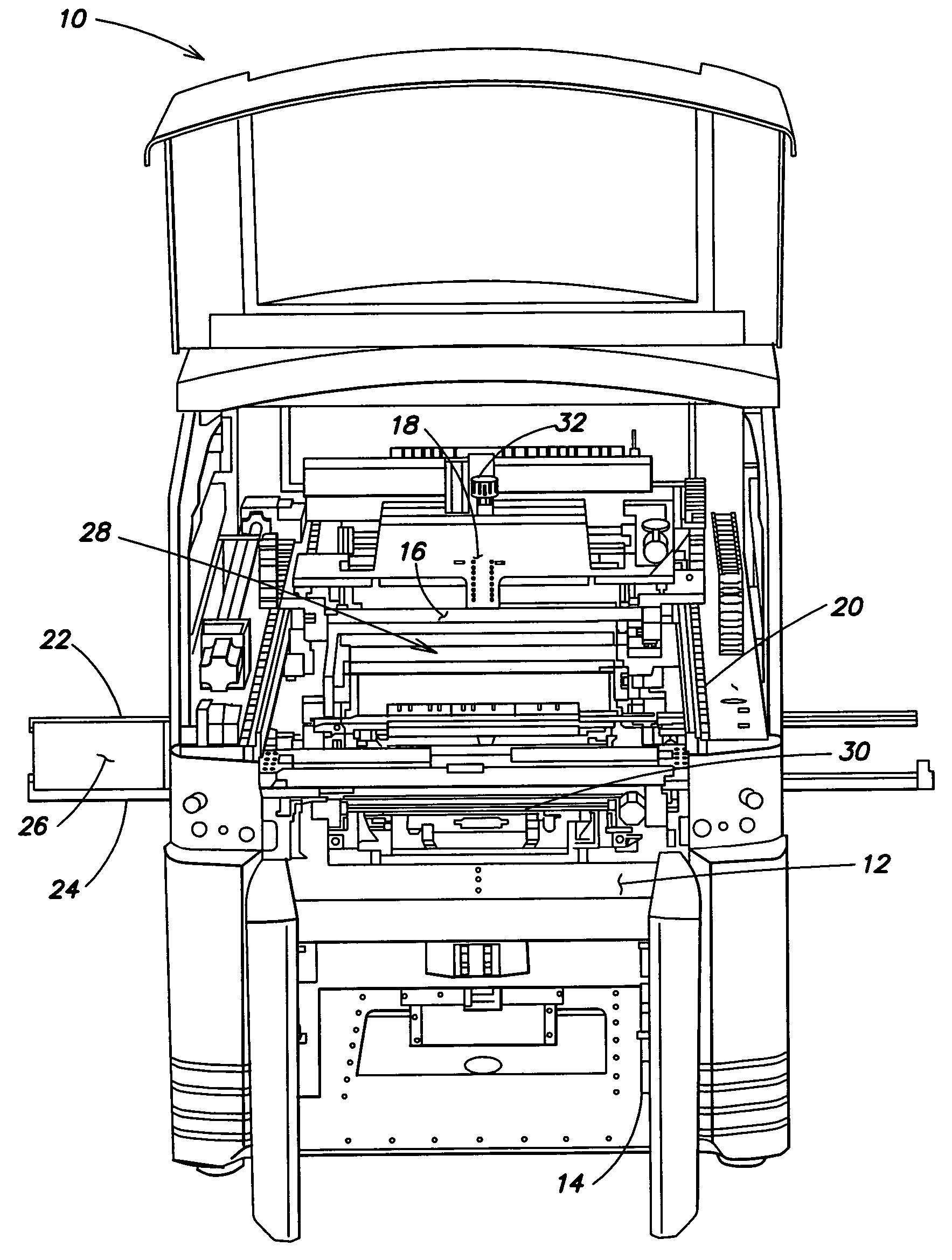
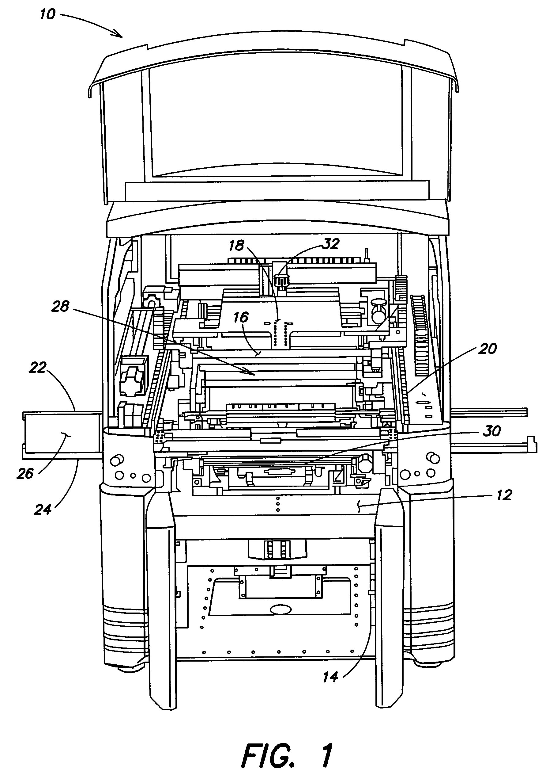
[0020]For purposes of illustration, embodiments of the present invention will now be described with reference to a stencil printer used to print solder paste onto a printed circuit board. One skilled in the art will appreciate, however, that embodiments of the present invention are not limited to stencil printers that print solder paste onto circuit boards, but rath...


PUM


Abstract

A stencil printer for printing viscous material on a substrate includes a frame, a stencil coupled to the frame, and a print head, coupled for the frame, to deposit and print viscous material over the stencil. The stencil printer further includes a substrate supporting and clamping assembly to support and clamp a substrate in a print position. The substrate supporting and clamping assembly includes at least one support member to support the substrate in a print position, a pair of rail members, coupled to the frame, adapted to engage opposite edges of the substrate, and a clamping mechanism, coupled to the frame, to move at least one of the rail members against the substrate to clamp the substrate. The clamping mechanism includes at least one piston to move the at least one of the rail members between a first position in which the rail member is spaced away from one of the opposite edges of the substrate and a second position in which the rail member engages one of the opposite edges of the substrate to clamp the substrate between the rail members during a print operation. The clamping mechanism further includes a pressure regulator to control a clamping force applied by the piston to the rail member against the edge of the substrate. A method for supporting and clamping a substrate in a print position is further disclosed.

Description

BACKGROUND OF INVENTION[0001]1. Field of Invention[0002]The present invention relates generally to substrate support assemblies for supporting and stabilizing a substrate within a machine that performs an operation on the substrate, and more particularly to a substrate support assembly of a stencil printer particularly designed to clamp edges of the substrate during a print operation.[0003]2. Discussion of Related Art[0004]In a typical surface-mount circuit board manufacturing operation, a stencil printer is used to print solder paste onto a printed circuit board. A circuit board, broadly referred to as an electronic substrate, having a pattern of pads or some other conductive surface onto which solder paste will be deposited, is automatically fed into the stencil printer. One or more small holes or marks on the circuit board, called fiducials, is used to properly align the circuit board with the stencil or screen of the stencil printer prior to the printing of solder paste onto the...

Claims


Application Information

Patent Timeline
Patent Type & Authority Patents(United States)
IPC IPC(8): B05C17/06
CPCB41F15/26H05K3/1216H05K2203/0165H05K3/12
Inventor PERAULT, JOSEPH A.LYNCH, JAMES
Owner SPEEDLINE TECH
Why Eureka
Try Eureka