Joint arrangement

a joint arrangement and joint technology, applied in the direction of couplings, traffic signals, roads, etc., can solve the problems of affecting the performance of the joint, and allowing an unwanted and substantial degree of movement of the joint, so as to achieve less weight, less deformation, and more conformity.

Active Publication Date: 2006-10-17
ROLLS ROYCE PLC
View PDF4 Cites 33 Cited by
  • Summary
  • Abstract
  • Description
  • Claims
  • Application Information

AI Technical Summary

Benefits of technology

[0008]Accordingly the present invention seeks to provide a novel gas turbine engine casing joint which is of less weight, deforms more readily, is more complian

Problems solved by technology

However, in the event that a blade becomes detached, the blade strikes the metal casing and a significant load is imparted from the main impact region of the metal casing to a flanged interface with an intake casing or rear fan casing.
Under impact by a released fan blade, the flanged joint between the metal casing and the intake or rear fan casing has a tendency to open thus permitting an unwanted and substantial degree of movement of the joint.
Furthermore it is a requirement for the bolts to resist the considerable shear force between

Method used


Image

  • Joint arrangement
  • Joint arrangement
  • Joint arrangement

Examples


first embodiment

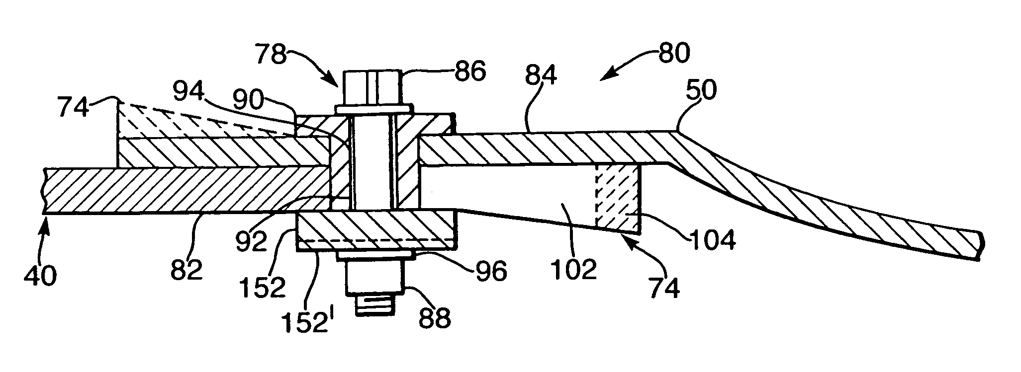
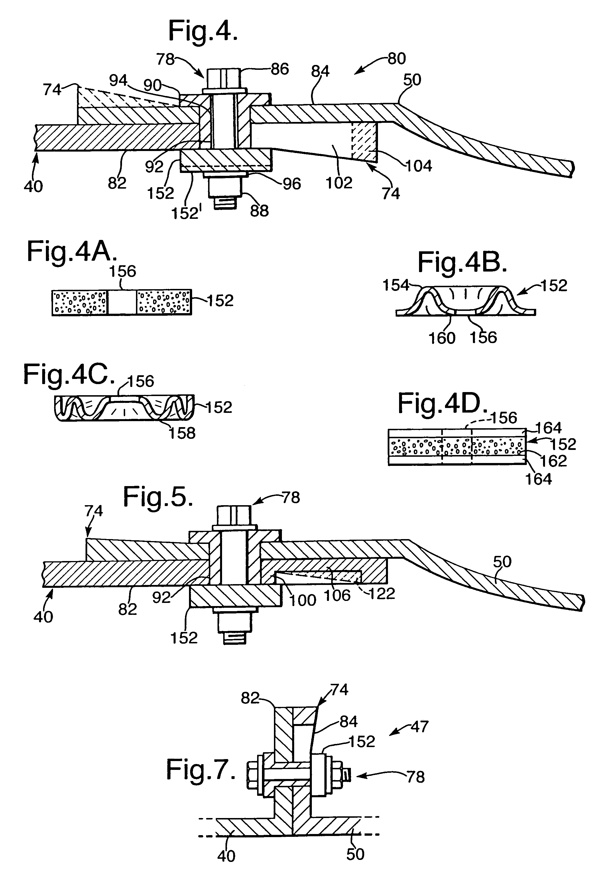
[0037]Referring now to FIG. 4, a joint arrangement 80 comprises overlapping portions 82 and 84 of the casing 40 and rear fan casing 50 respectively. The joint arrangement is an exemplary embodiment of the present invention and is intended to replace the prior art flanged joint 47 (and 41). In this first embodiment a first member is defined by the metal casing 40 and a second member is defined by the rear fan casing 50. The first and second members 40, 50 define the overlapping portions 82, 84. In this example the overlapping portions 82, 84 are arranged in conventional fashion and are generally annular in configuration although that is not necessary for other applications of the present invention. The overlapping portions 8284 are secured together by a hollow pin 90, inserted through corresponding radially aligned holes 92 and 94 defined therein respectively. A bolt 86 extends through the hollow pin 90 and co-operates with a nut 88 and washer 96 in conventional fashion to secure the...

third embodiment

[0050]Referring to FIG. 6, the joint arrangement 80 of this third embodiment comprises the casing 40 defining a tongue portion 170 which cooperates with a groove portion 172 defined by the rear fan casing 50. Like elements are given like numerals as shown in other Figures and operate in similar manner. Each overlapping portion 174 or annular finger 174 of the groove portion 172 comprises a wedge shaped portion 74. The securing means 78 comprises a deformable member 152 disposed between the annular finger 174 and bolt 86 and nut 88 respectively.

[0051]The deformable members 152 are preferably identical as are the wedge shaped portion 74. However, the deformable members 152 may be of different compressibility so as to have an overall increase in resistance part way along the full axial extension of the joint.

[0052]Alternatively, only one annular finger comprises a wedge shaped portion 74 and only one deformable washer 152 may be provided.

[0053]A further aspect of the present invention ...

fourth embodiment

[0055]A fourth embodiment in FIG. 7 comprises the present invention applied to a conventional bolt flange joint 47. The securing means 78 is configured as any other embodiment described herein as are the overlapping portions 82, 84. This embodiment is employed where any axial movement required during a fan blade off event is accommodated by another feature elsewhere on the casing 40, containments casing 38 or rear fan casing 50. Essentially this joint is capable of accommodating radial loads in similar fashion to the previous embodiments that substantially accommodate relative axial displacements between overlapping portions.


PUM


Abstract

A joint assembly 80 is provided for limiting an extension of the joint 80 in the direction of a load path derived from an impact comprising. In its simplest form, the joint 80 comprises a first member 40 having a portion 82 and a second member 50 having a portion 84, the portions 82, 84 overlapping one another and arranged generally parallel to one another and secured together via securing means 78. The securing means 78 is disposed through corresponding holes 92, 94 defined by portions 82 and 84. At least one of the overlapping portions 82 or 84 further defines, sequentially in the direction of extension a pocket 102. The securing means 78 comprises a deformable member 152, 178 and at least one of the overlapping portions 82, 84 comprises a wedge-shaped portion 74. In the event of a worst-case impact load the securing means 78 is forced through the pocket 106 while the wedge-shaped portion 74 causes the deformable member 152 to deform and thereby increase the clamping force, in a progressive manner, to limit the extension of the joint assembly 80 and retain an integral joint assembly 80.

Description

FIELD OF THE INVENTION[0001]The present invention relates to a joint arrangement for limiting an extension of the joint generally in the direction of a load path derived from an impact load. In particularly, but not exclusively, the joint is used for a gas turbine engine fan casing and more particularly to an improved casing joint arrangement for use within or forming a part of the gas turbine engine blade containment assembly.BACKGROUND OF THE INVENTION[0002]Turbofan gas turbine engines for powering aircraft conventionally comprise a core engine, which drives a fan. The fan comprises a number of radially extending fan blades mounted on a fan rotor which is enclosed by a generally cylindrical, or frustoconical, fan casing. The core engine comprises one or more turbines, each one of which comprises a number of radially extending turbine blades enclosed by a cylindrical, or frustoconical, casing.[0003]There is a remote possibility with such engines that part, or all, of a fan blade, o...

Claims


Application Information

Patent Timeline
IPC IPC(8): F16D1/00F01D21/04
CPCF01D21/045Y02T50/671Y10T403/642Y10T403/49Y10T403/645Y10T403/11Y10T403/75Y10T403/64F16B2200/50F16B2200/503F16B2200/506Y02T50/60F16B2200/63
Inventor MCMILLAN, ALISON JWHITE, KEVIN A
Owner ROLLS ROYCE PLC
Why Eureka
Try Eureka