System for in-situ control of the orientation of a vehicle headlamp and process for its implementation

a technology for in-situ control and vehicle headlamps, which is applied in process and machine control, optical apparatus testing, instruments, etc., can solve the problems of significant investment of time and money, liable to dazzle the drivers of vehicles coming in the opposite direction, and the driver of the vehicle then no longer has sufficient visibility to properly judge the road conditions

Active Publication Date: 2006-10-17
VALEO VISION SA
View PDF10 Cites 18 Cited by
  • Summary
  • Abstract
  • Description
  • Claims
  • Application Information

AI Technical Summary

Problems solved by technology

They are then liable to dazzle the drivers of vehicles coming in the opposite direction.
The driver of the vehicle then no longer has sufficient visibility to properly judge the road conditions.
However, this system has a number of drawbacks.
Thus, the operation to fit the sensors during manufacture of the vehicle calls for a high degree of precision, and consequently entails significant investment of time and money.

Method used


Image

  • System for in-situ control of the orientation of a vehicle headlamp and process for its implementation
  • System for in-situ control of the orientation of a vehicle headlamp and process for its implementation
  • System for in-situ control of the orientation of a vehicle headlamp and process for its implementation

Examples


Embodiment Construction

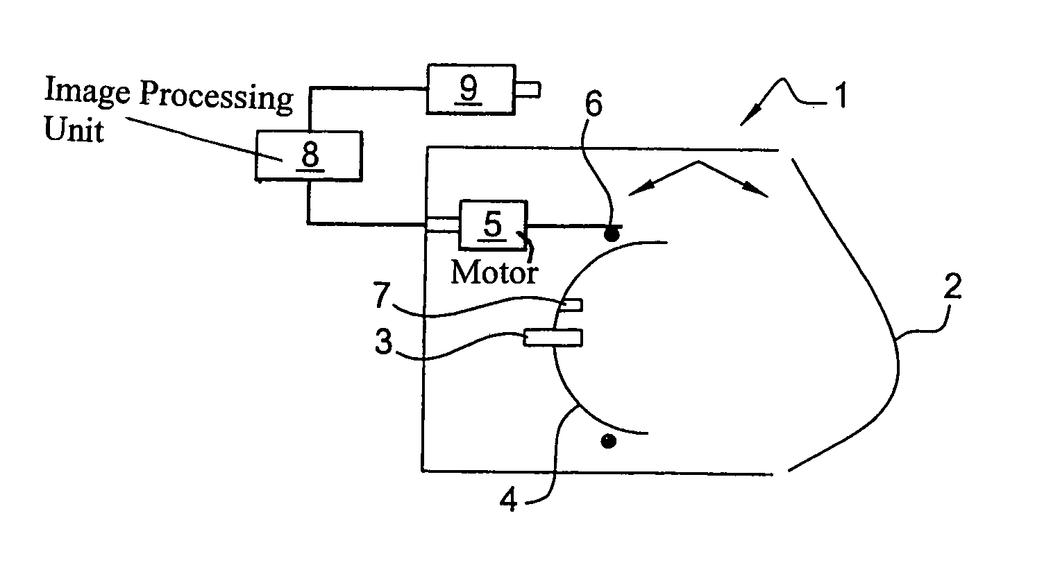
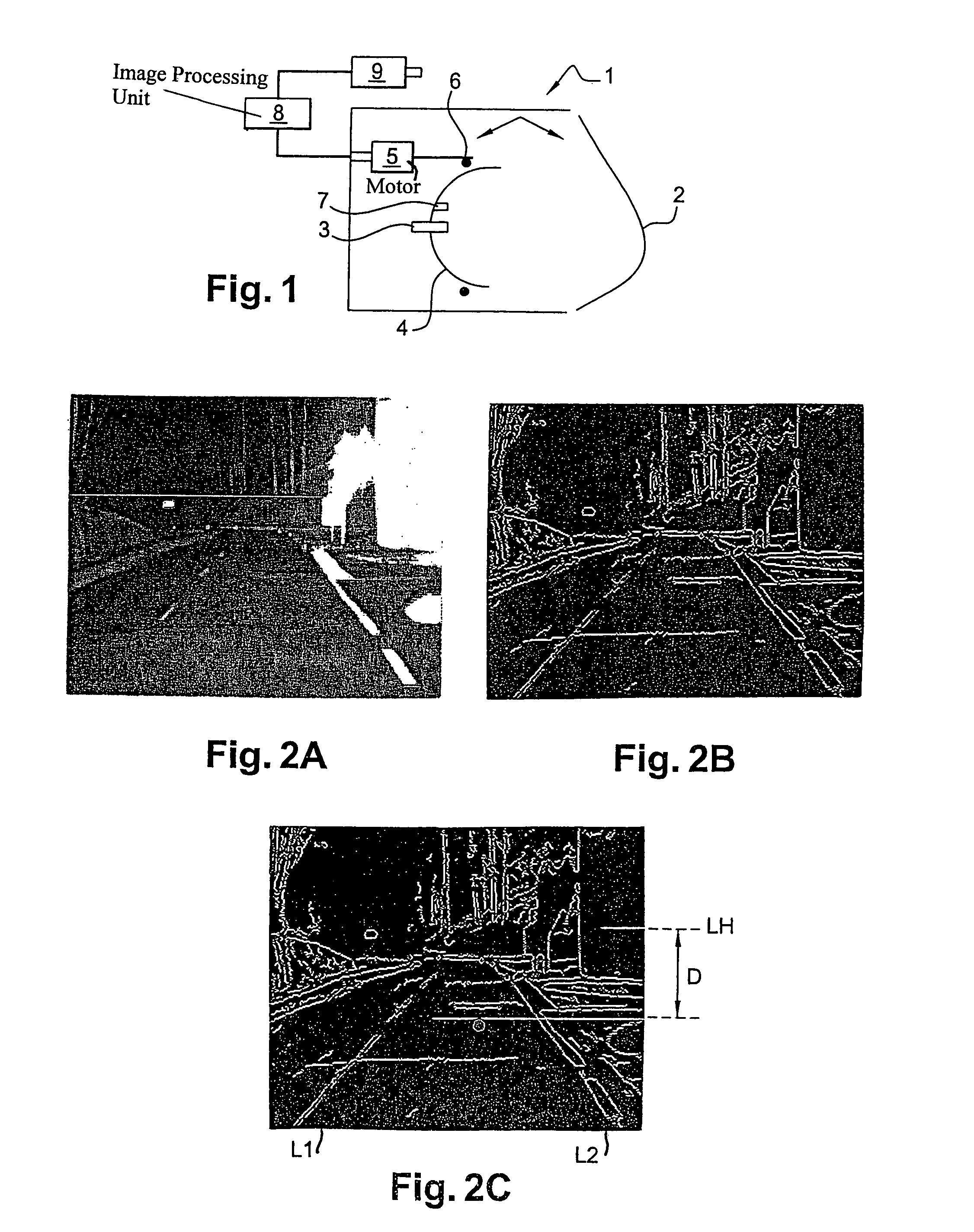
[0023]FIG. 1 illustrates a low-beam headlamp of a vehicle, equipped with an orientation control system according to the invention. More precisely, FIG. 1 shows a headlamp 1 fitted with a lens 2 (lamp closure glass possibly in conjunction with optical components such as lenses not shown) and a light source 3 mounted on a mobile support 4. This mobile support 4 is the reflector of the headlamp. This reflector 4 is actuated by a motor 5 associated with a rotation device 6, such as a ball joint. Inside the headlamp 1, arrows indicate the rotational movement of the reflector 4 and, notably, of the light source 3 integral with the reflector 4. This light source 3 can be a conventional light source for a vehicle headlamp. Similarly, the reflector 4, the lens 2, the motor 5 and the rotation device 6 can be conventional components as used in a low-beam headlamp for a vehicle.

[0024]The reflector 4 is also fitted with a second light source 7 which, as will be explained below, is a light source...


PUM


Abstract

The invention relates to a system for in-situ control of the orientation of a vehicle headlamp equipped with a light source fixed on a mobile reflector, and including a camera mounted in the vehicle, an image processing unit connected to the camera, and a specific light point emission device. It also relates to a process for in-situ control of the orientation of a vehicle headlamp, wherein it includes the following operations: recording of successive images of a scene extending in front of the vehicle, processing of at least one image of the scene and production of a processed image, determination, from this processed image, of a horizon line of the scene, determination of a specific point in the scene located at a pre-defined distance D from the horizon line, adjustment of the headlamp until this specific point is located in the light beam emitted by the headlamp.

Description

FIELD OF THE INVENTION[0001]The invention relates to a system to control the orientation of a vehicle headlamp in-situ, providing constant illumination of the road irrespective of the attitude of the vehicle. The invention also relates to a process enabling this control system to be implemented.[0002]The invention finds applications in the field of road vehicles such as, for example, cars or heavy goods vehicles. In particular, it finds applications in the field of light projection by these vehicles onto the road.PRIOR ART[0003]Currently, all vehicles travelling on the road include a device for illumination of the road used particularly at night or in bad weather. Conventionally, cars are equipped with two types of lighting: lighting termed “high beam” which illuminates the entire road over a long distance, and lighting termed “low beam” which illuminates the road over a short distance to avoid dazzling drivers of vehicles which may be travelling in the opposite direction. High-beam...

Claims


Application Information

Patent Timeline
Patent Type & Authority Patents(United States)
IPC IPC(8): B60Q1/04B60Q1/115B60Q1/08B60R1/00B60Q1/10B60Q1/14G01M11/06
CPCB60Q1/10G01M11/068B60Q2300/132B60Q2300/324
Inventor BRUN, NORBERTLELEVE, JOEL
Owner VALEO VISION SA
Why Eureka
Try Eureka