Non-swirl dry low NOx (DLN) combustor

a combustor and air/fuel technology, applied in the ignition of turbine/propulsion engines, combustion types, lighting and heating apparatus, etc., can solve the problems of swirlers being highly susceptible to acoustic combustion instability, combustion chambers and air plenums within the combustor lack sufficient damping to avoid acoustical instabilities, etc., to eliminate acoustical instabilities and flashbacks

Active Publication Date: 2006-10-31
THE BOEING CO +1
View PDF76 Cites 24 Cited by
  • Summary
  • Abstract
  • Description
  • Claims
  • Application Information

AI Technical Summary

Benefits of technology

[0010]An improved pre-mixer for a gas turbine combustor and a method of pre-mixing air and fuel for a combustor are provided by the present invention. The improved “non-swirl” combustors described herein eliminate the acoustical instabilities and flashbacks associated with the previous devices. The new combustors provided by the present invention employ multi-element, microfine injector technology adapted herewith for turbine combustor applications. Moreover, the present invention provides NOx and CO emissions as low as 3 ppm and 5 ppm, respectively, at full power and even at low turndown ratios as low as 5 and 10 ppm respectively.

Problems solved by technology

At best, however, such technology generally obtains NOx emissions as low as 25 ppm.
Clearly, such technology falls short of the current upper limit of 3 ppm NOx emissions.
These swirlers are highly susceptible to acoustic combustion instability.
Accordingly, the combustion chamber and air plenums within the combustor lack sufficient damping to avoid acoustical instabilities.
Furthermore, pre-mix swirlers are very susceptible to detrimental combustion flashback during turn-down and start-up operation because of their large characteristic dimension (e.g., above 1.0 inch).
Flashback, via the associated internal combustion in the swirler, frequently damages the swirler by overheating it.
Another problem with the previously implemented swirl combustors occurs during power turn-down wherein the overall fuel flow is reduced to equivalence ratios below 0.4.
Hence, during turndown operation, swirler combustors inherently produce excessive amounts of carbon monoxide (well above the adiabatic equilibrium combustion amounts of approximately 3 ppm).

Method used


Image

  • Non-swirl dry low NOx (DLN) combustor
  • Non-swirl dry low NOx (DLN) combustor
  • Non-swirl dry low NOx (DLN) combustor

Examples


Embodiment Construction

[0020]The following description of the preferred embodiment(s) is merely exemplary in nature and is in no way intended to limit the invention, its application, or uses.

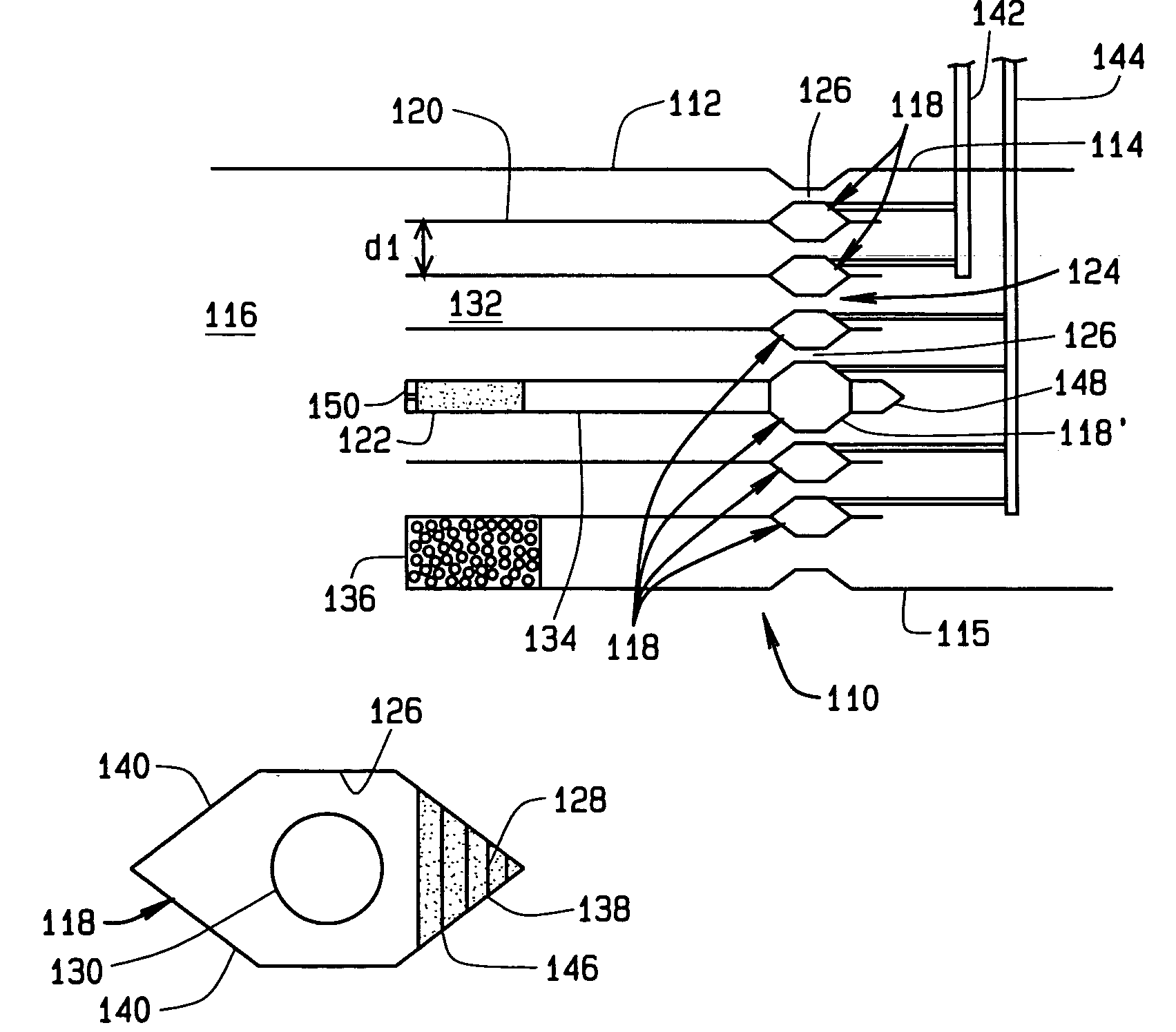
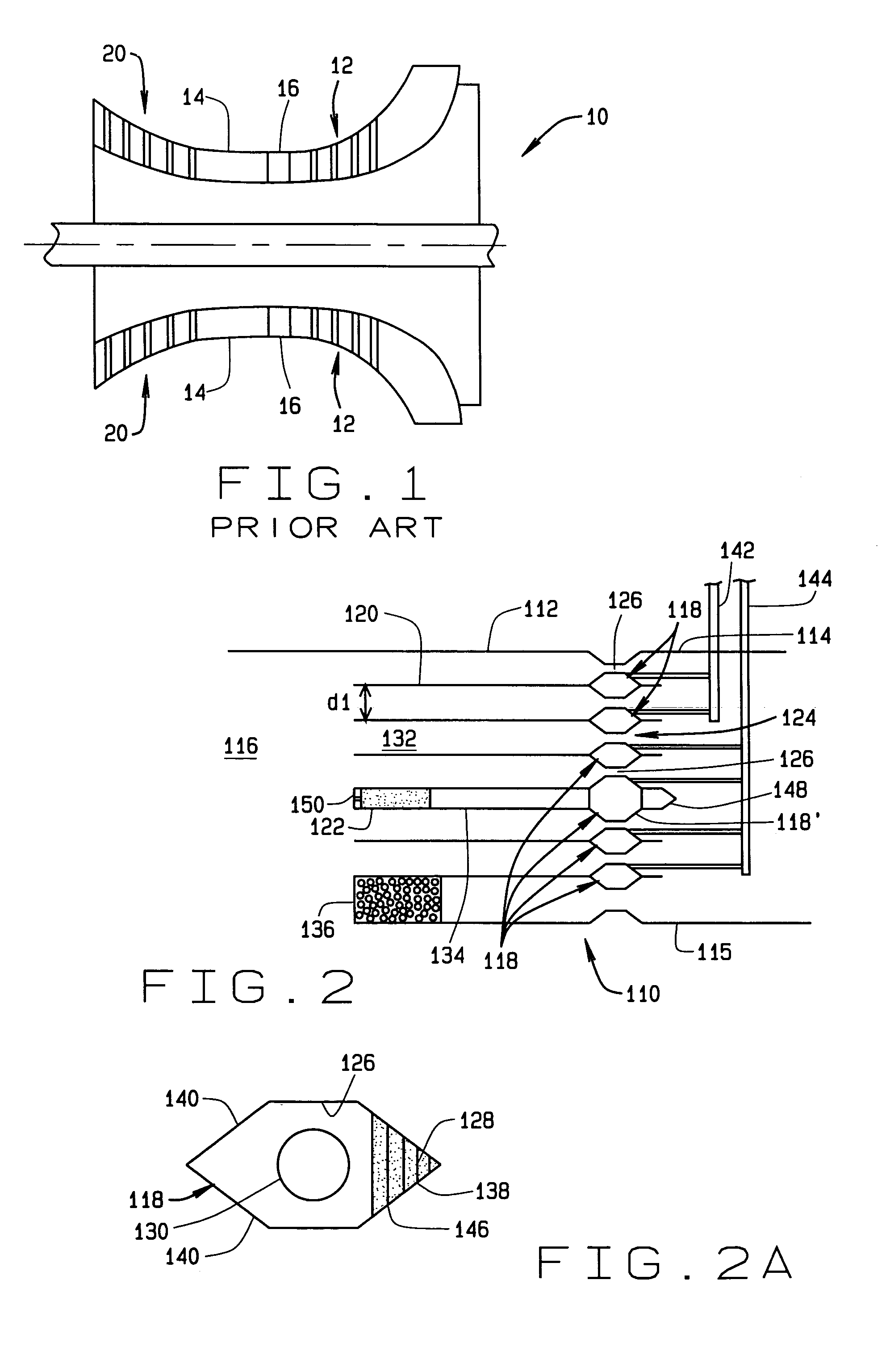
[0021]The current invention solves the high NOx and superequilibrium CO emission, acoustic instability, and flashback problems associated with the previous combustors by employing numerous small scale (less than 0.150-in.) non-swirl multi-element pre-mix injectors. In accordance with the principles of the present invention these injectors also incorporate diffusion pilots.

[0022]Additionally, by maintaining very low mixing lengths within a single diffusion pilot, and among multiple diffusion pilots, the present invention minimizes the high temperature recirculation flame holding zones of the pilots. Additionally, the present invention also provides adequate flammability and flame stabilization for the combustor system while minimizing those holding zones.

[0023]Moreover, rather than using all of the air side pressure dr...


PUM


Abstract

An air / fuel pre-mixer for a gas turbine combustor and a method of pre-mixing air and fuel for a combustor are provided. In one embodiment the pre-mixer includes a first annular premix fuel manifold disposed upstream of the combustor and an annular member concentric with the first premix fuel manifold. Together the annular premix fuel manifold and the annular member define a first venturi shaped air / fuel pre-mix volume between them that has a throat. At or upstream from the throat, the first premix fuel manifold has a plurality of pores whereby the fuel is injected from the first premix fuel manifold to mix with air in the first pre-mix volume. In another embodiment, the annular member is an outer wall, whereas in yet another embodiment, the annular member is a second premix fuel manifold.

Description

FIELD OF THE INVENTION[0001]The present invention relates to air / fuel pre-mixers for combustors, and more particularly to non-swirl air / fuel pre-mixers for stationary gas turbine combustors.BACKGROUND OF THE INVENTION[0002]The U.S. stationary power industry is continually being required to lower its pollution levels, especially those of nitrogen oxide gas (NOx), to very low levels. Currently, the industry standard for NOx emissions ranges from 3 to 20 parts per million (ppm). However, federal and state environmental protection agencies are now demanding exhaust emission levels to 3 ppm or below in most areas of the country. Thus, a combustor delivering NOx levels below 1 ppm would likely become certified as the “Best Available Technology” for lowering NOx levels.[0003]Some prior art combustors employ a single central diffusion pilot swirler operating at equivalence ratios between 0.8 and 1.2 surrounded by eight premix swirlers operating at equivalence ratios of approximately 0.4. Ot...

Claims


Application Information

Patent Timeline
Patent Type & Authority Patents(United States)
IPC IPC(8): F23R3/30F23D3/40F23D7/00F23D11/38F23R3/28F23R3/34
CPCF23D3/40F23D7/00F23D11/38F23R3/286F23R3/343F23D2209/10F23D2214/00F23D2900/00014
Inventor SPROUSE, KENNETH M.FARHANGI, SHAHRAMHORN, MARK D.MATTHEWS, DAVID R.
Owner THE BOEING CO
Why Eureka
Try Eureka