
Imaging device having stand connection

a technology of imaging device and stand, which is applied in the direction of instruments, furniture parts, machine supports, etc., can solve the problems of poor coupling between the camera and the stand, bad effect on the appearance of the camera, and difficulty in forming a suitable connector therein, so as to achieve convenient and secured photographing and better appearance

Inactive Publication Date: 2006-10-31
SAMSUNG ELECTRONICS CO LTD
View PDF3 Cites 25 Cited by
  • Summary
  • Abstract
  • Description
  • Claims
  • Application Information

AI Technical Summary

Benefits of technology

[0006]The present invention provides an imaging device having a stand connecting structure that can assume a closed configuration when a stand is not coupled to the imaging device, and an open configuration when coupling with the stand. This can provide a better appearance and ensure easy and secured photographing.

Problems solved by technology

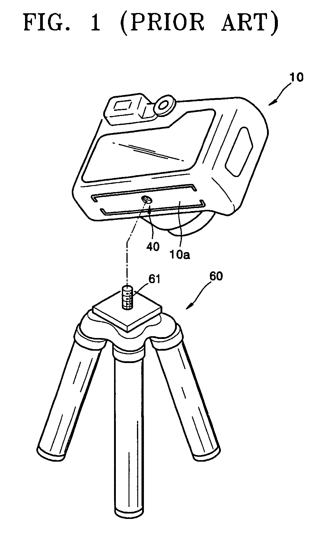
In this structure, the connector 40 seeing from the out surface of the camera 10 may cause bad effects on the appearance of the camera 10.
In addition, foreign substances may be introduced into the camera 10 through the screw hole of the connector 40, thereby causing poor coupling between the camera 10 and the tripod 60.
However, compact imaging devices such as mobile phones and small cameras often have a narrow bottom surface, making it difficult to form therein a suitable connector (such as connector 40 as in FIG. 1) for coupling a tripod because of the space limitations.
When the imaging devices are used for shooting without fixing to the tripod, the imaging device (e.g., a mobile phone) may shake during shooting, leading to obtain a bad or blurred image.
More serious results can be caused if the imaging device is held by hand for a long period of time to take a video or to take a self-photograph, for example.

Method used


Image

  • Imaging device having stand connection
  • Imaging device having stand connection
  • Imaging device having stand connection

Examples


Embodiment Construction

[0020]The present invention will now be described more in details with reference to the accompanying drawings, in which preferred embodiments of the invention are shown.

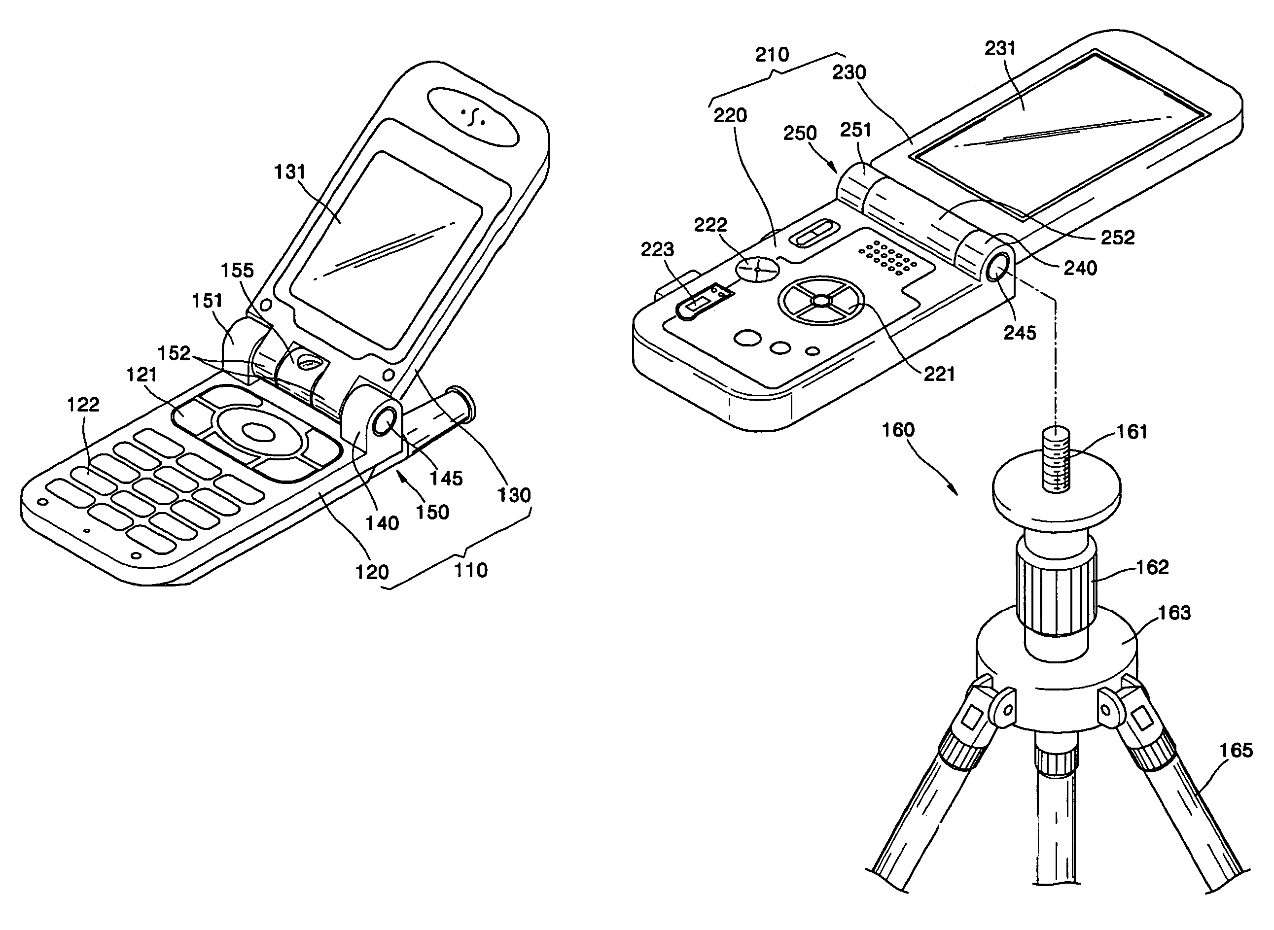
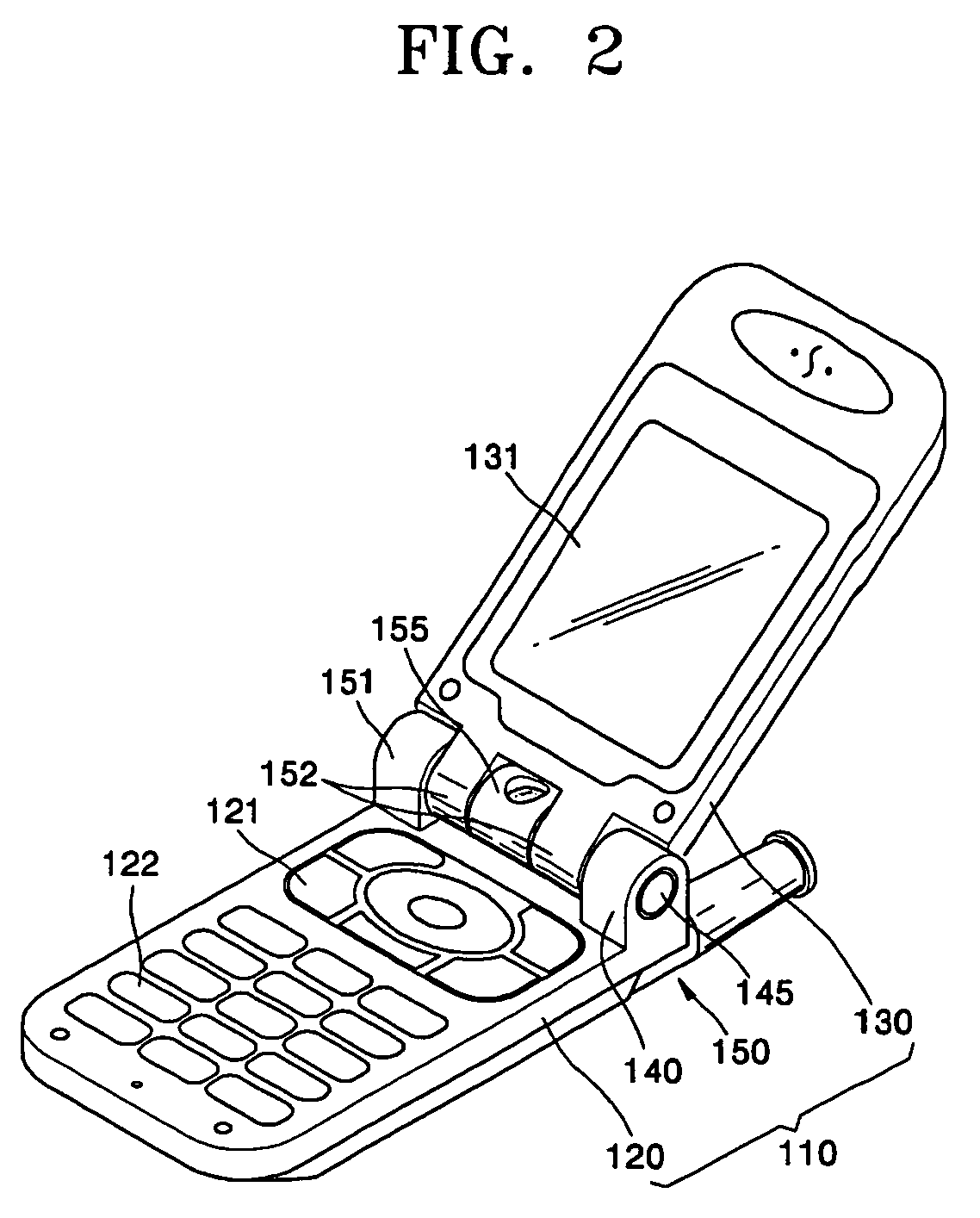
[0021]FIG. 2 is a perspective view of an imaging device such as a folder-type mobile phone 110 constructed according to one embodiment of the present invention. The mobile phone 110 includes a main body 120 and a folder cover 130. The main body 120 and the folder cover 130 are connected by a hinge member 150 such that the folder cover 130 rotates about the hinge member 150 to open and close relative to the main body 120.

[0022]The folder cover 130 includes a display panel 131 on which information stored in the mobile phone 110 or other pertinent information is displayed, and the main body 120 includes navigation keys 121 and alphanumeric keypads 122 for user entry of information and selection of modes, and the like.

[0023]The hinge member 150 includes folder coupling parts 152 formed on a lower end of the folder cover ...


PUM


Abstract

Provided is an imaging device having a stand connector that can assume an open position for allowing connection with a stand or tripod and a closed position when not coupled with the stand. The stand connector of the imaging device includes a connector body including a hollow cavity and a female screw capable of coupling with a corresponding male screw of the stand, an insert received in the cavity of the connector body and moveable between an open position allowing coupling of the stand by screwing the screws of the connector body and the stand and a closed position substantially covering an open end of the cavity in the connector body when not coupling with the stand, and biasing means configured to bias the insert to the closed position.

Description

BACKGROUND OF THE INVENTION[0001]This application claims priority of Korean Patent Application No. 10-2004-0089206, filed on Nov. 4, 2004, in the Korean Intellectual Property Office, the disclosure of which is incorporated herein in its entirety by reference.FIELD OF THE INVENTION[0002]The present invention relates to an imaging device having a connection structure for coupling with a stand (e.g., a tripod), and more particularly, to an imaging device having a stand connection structure which can assume a closed configuration when the stand is not coupled to the imaging device.DESCRIPTION OF THE RELATED ART[0003]In general, to capture a still image or a moving image of an object accurately and stably, imaging devices such as cameras and camcorders are affixed on a tripod for standing on the ground such that the imaging devices can be placed without movement during shooting for taking an object image with the imaging devices.[0004]FIG. 1 is a perspective view illustrating a state for...

Claims


Application Information

Patent Timeline
Patent Type & Authority Patents(United States)
IPC IPC(8): A47B91/00
CPCH04M1/0214H04M1/0218H04M1/04H04M2250/52H04B1/38H04B1/40
Inventor LEE, EUN-KYUNG
Owner SAMSUNG ELECTRONICS CO LTD
Learn More