
Measurement of torsional dynamics of rotating shafts using magnetostrictive sensors

a magnetostrictive sensor and torsional dynamics technology, applied in the direction of work measurement, measurement devices, instruments, etc., can solve the problems of not only difficult to use but costly to implement, and the available methods generally lack long-term durability, so as to increase the stress sensitivity of the detector, low cost and long-term

Inactive Publication Date: 2006-11-07
SOUTHWEST RES INST
View PDF16 Cites 34 Cited by
  • Summary
  • Abstract
  • Description
  • Claims
  • Application Information

AI Technical Summary

Benefits of technology

The present invention is about methods and devices for measuring dynamic torsion in a rotating shaft using magnetostrictive sensors. The invention provides a low-cost and long-term sensor for acquiring dynamic data of the shaft portion of a machinery system being monitored and / or controlled. The invention utilizes an inductive pickup coil positioned to encircle the rotating shaft and a permanent biasing magnet to maintain the magnetostrictive material magnetized, which increases the stress sensitivity of the detector and makes its frequency response linear with stress. The detected signals are conditioned using standard electronic signal conditioning circuitry for subsequent processing in a data processor to develop the desired dynamic torsional data.

Problems solved by technology

In many situations, these methods are not only difficult to use but costly to implement.
In addition, the available methods generally lack long-term durability, which is essential for on-line monitoring and control during the service life of high speed rotational machinery.
None of these efforts, however, disclose or anticipate a detector that does not include some form of periodic external excitation of the magnetostrictive material.

Method used


Image

  • Measurement of torsional dynamics of rotating shafts using magnetostrictive sensors
  • Measurement of torsional dynamics of rotating shafts using magnetostrictive sensors
  • Measurement of torsional dynamics of rotating shafts using magnetostrictive sensors

Examples


Embodiment Construction

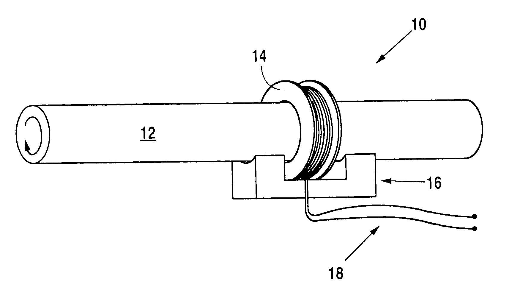
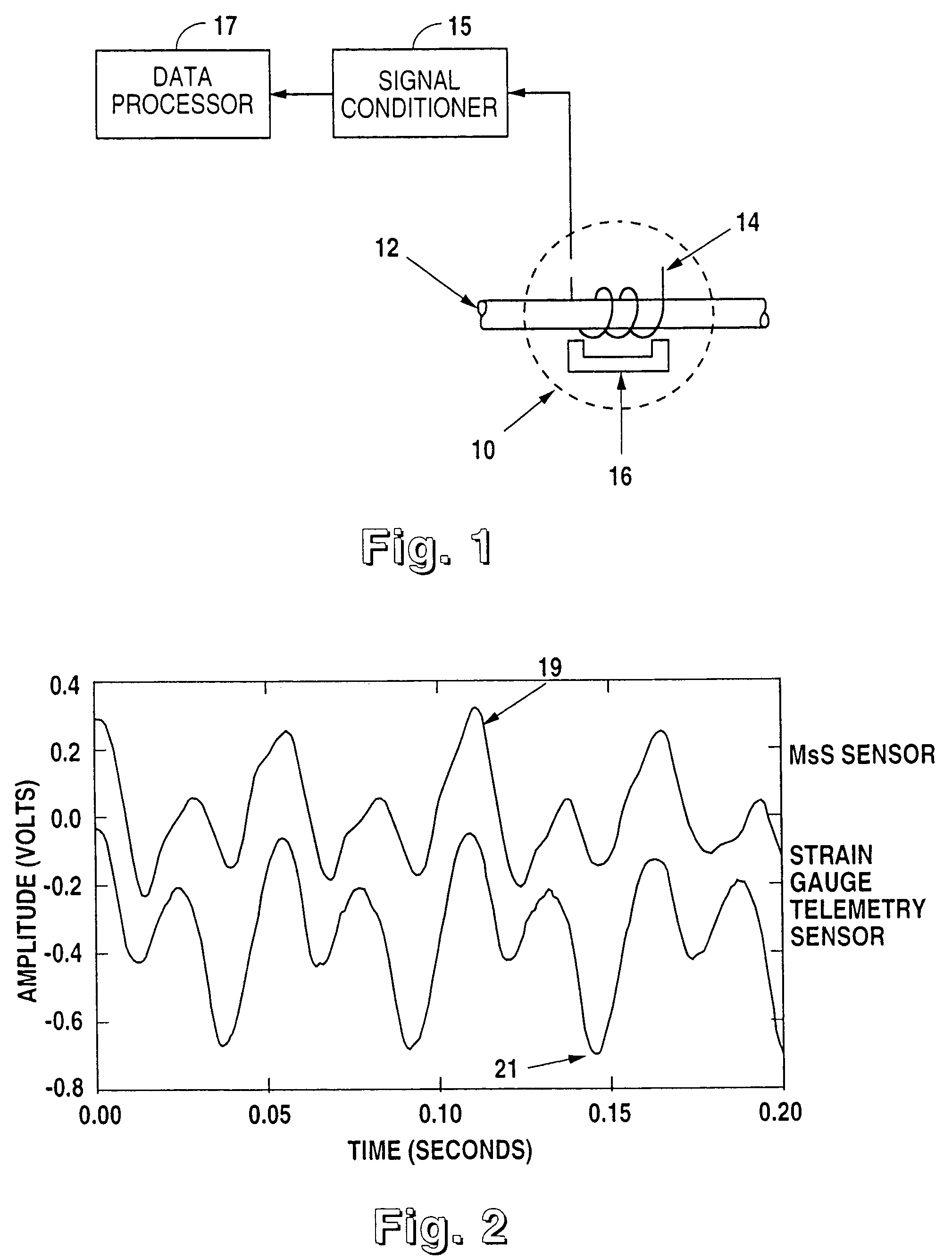
[0034]In the present invention, measurements of the torsional dynamics of a rotating shaft are accomplished without making physical contact with the shaft through the use of a magnetostrictive sensor (MsS). FIG. 1 illustrates the basic configuration of a MsS together with the accompanying electronics for signal conditioning. Since the MsS relies on a physical phenomenon known as the Villari effect (which refers to magnetic induction changes resulting from mechanical stress) peculiar to the ferromagnetic materials, the invented method is applicable to shafts made of ferromagnetic materials. If the shaft is not made of ferromagnetic materials, the invented method is still applicable by plating or adhesively bonding the shaft with a suitable ferromagnetic material such as nickel. In this case, the plating or adhesive bonding is necessary only in the local area on which the MsS is placed.

[0035]Signal detector (14) in FIG. 1 is a magnetic field sensing device, typically an inductive pick...


PUM

PropertyMeasurementUnit
diameteraaaaaaaaaa
diameteraaaaaaaaaa
diameteraaaaaaaaaa

Abstract

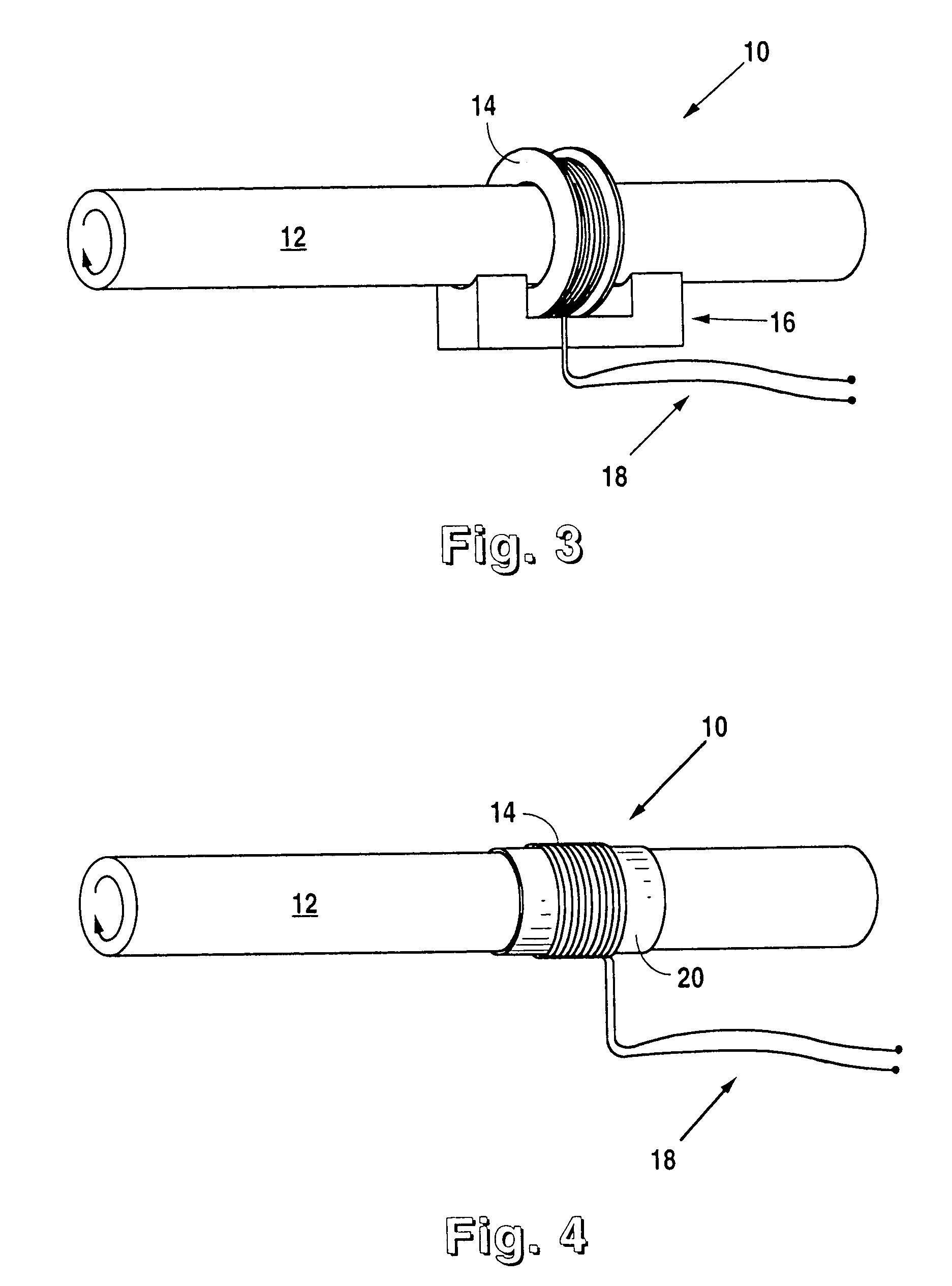
A device and method for the non-contact measurement of dynamic torsion in a rotating shaft using magnetostrictive sensors (MsS). The monitoring and detection system have specially configured magnetostrictive signal detectors that include inductive pickup coils, in which signals corresponding to localized shaft torques are induced. The non-contact method for measuring dynamic torques includes fixing a ferromagnetic strip to a ferromagnetic or non-ferromagnetic shaft and inducing a circumferential residual magnetization therein. An MsS in the form of either an encircling coil positioned around the shaft on a cylindrical substrate, or a partially encircling coil positioned on a flexible substrate and wrapped partially about the shaft.

Description

CROSS REFERENCE TO RELATED APPLICATIONS[0001]This application is a continuation-in-part, under 35 USC §120 of co-pending U.S. patent application Ser. No. 09 / 355,177 filed Jul. 27, 1999 , which further claims the benefit under 35 USC §119(e) of U.S. Provisional Patent Application No. 60 / 036,039 filed Jan. 27, 1997, which also is a 371 of PCT / US98 / 01297, filed Jan. 23, 1998.BACKGROUND OF THE INVENTION[0002]I. Field of the Invention.[0003]The present invention relates generally to methods and devices for the non-contact monitoring and measurement of the torsional dynamics of rotating shafts. The present invention relates more specifically to methods and devices for the non-contact monitoring and measurement of stationary and transient torques in rotating shafts using magnetostrictive sensors (MsS).[0004]II. Description of the Prior Art.[0005]It is common in many different machine systems, for mechanical power from an electrical motor, combustion engine, or gas turbine to be transmitted...

Claims


Application Information

Patent Timeline
Patent Type & Authority Patents(United States)
IPC IPC(8): G01L3/02G01L3/10
CPCG01L3/102G01L3/105
Inventor KWUN, HEGEONKIM, SANG-YOUNG
Owner SOUTHWEST RES INST
Learn More