
Drive temperature self-adjustment for temperature-sensitive measurements

a technology for temperature-sensitive measurements and drives, applied in the field of storage systems, can solve problems such as item failure, item failure, and and achieve the effect of preventing the failure of the write-off head and preventing the failure of the driv

Inactive Publication Date: 2006-11-14
HITACHI GLOBAL STORAGE TECH NETHERLANDS BV
View PDF21 Cites 19 Cited by
  • Summary
  • Abstract
  • Description
  • Claims
  • Application Information

AI Technical Summary

Problems solved by technology

On / off failures are failures in which an item fails, such as a cable breaks, a disk does not spin, a read / write head does not function at all, etc.
Such failures are easy to identify and locate, but may require putting the HDD in an artificial condition, such as temperature extremes, high vibration, etc., that makes such an on / off failure more likely.
Such conditions can cause undetected damage to the HDD, and thus on / off failure analysis has inherent limitation.
Gradual performance degradation occurs before an on / off failure.
While such performance degradation may be caused by the same conditions that cause an on / off failure, evaluation of gradual performance degradation is typically performed under conditions much less severe than those that may cause an on / off failure.
That is, a GEM may detect an increase in the distance between a read / write head and a disk surface, or an increase in noise in a digital signal read by the read / write head, but such increases do not cause a failure of the entire HDD or an HDD component, and thus are not considered “errors.” Nonetheless, such GEMs are good indicators of potential problems, especially if the conditions causing the GEMs are allowed to persist or increase.
For example, if the distance between the read / write head and disk surface (known as the “flying height” of the head) increases beyond an expected tolerance as the operating temperature of the disk surface increases, then a failure can be predicted if the temperature continues to rise beyond the normal operating temperature or remains at the normal operating temperature for an extended period of time.
Such heaters / coolers require additional test bench footprint space, electrical outlets, feedback controls, and cost.
However, such fans can only cool, not warm up the HDD.

Method used


Image

  • Drive temperature self-adjustment for temperature-sensitive measurements
  • Drive temperature self-adjustment for temperature-sensitive measurements
  • Drive temperature self-adjustment for temperature-sensitive measurements

Examples


Embodiment Construction

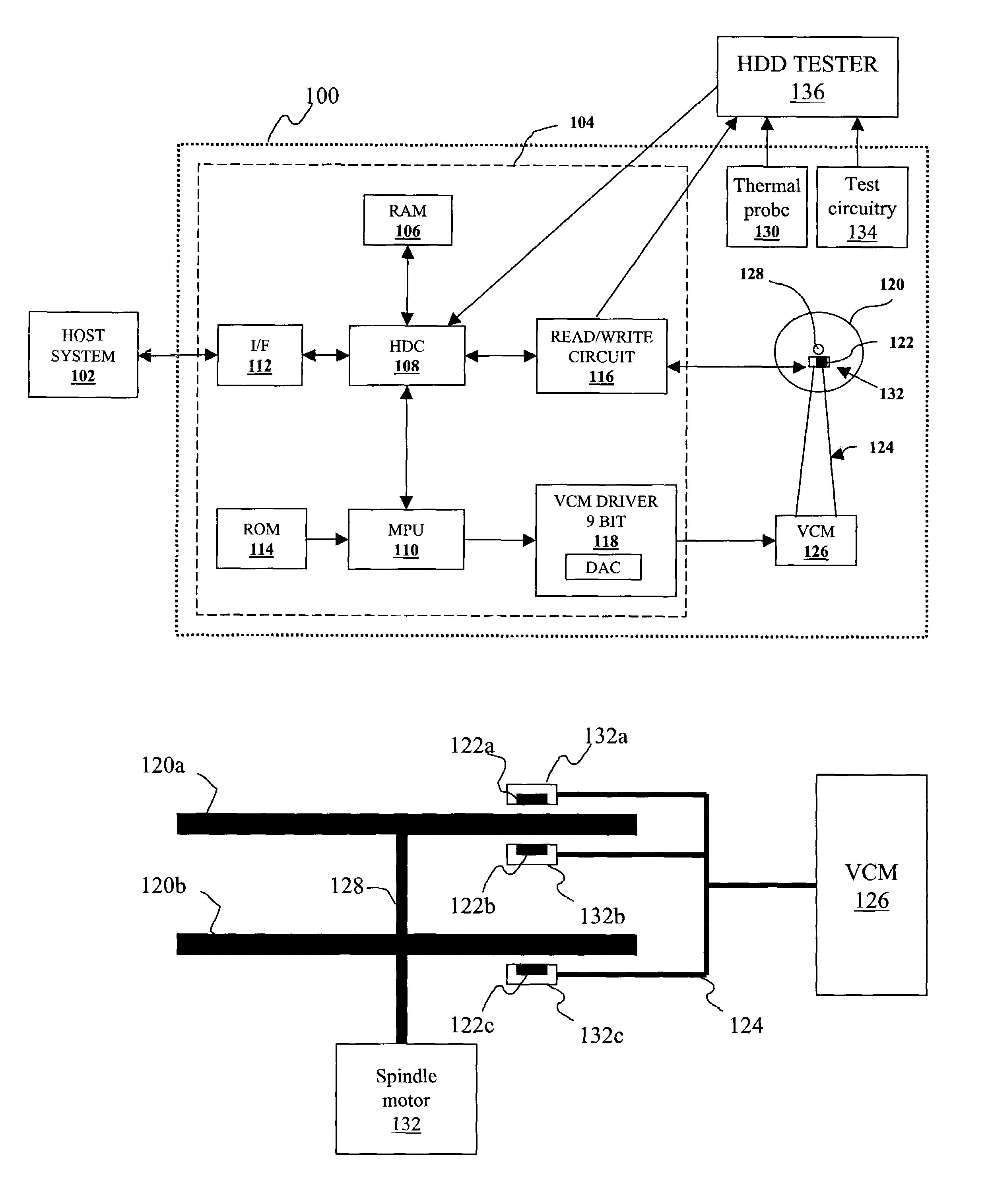
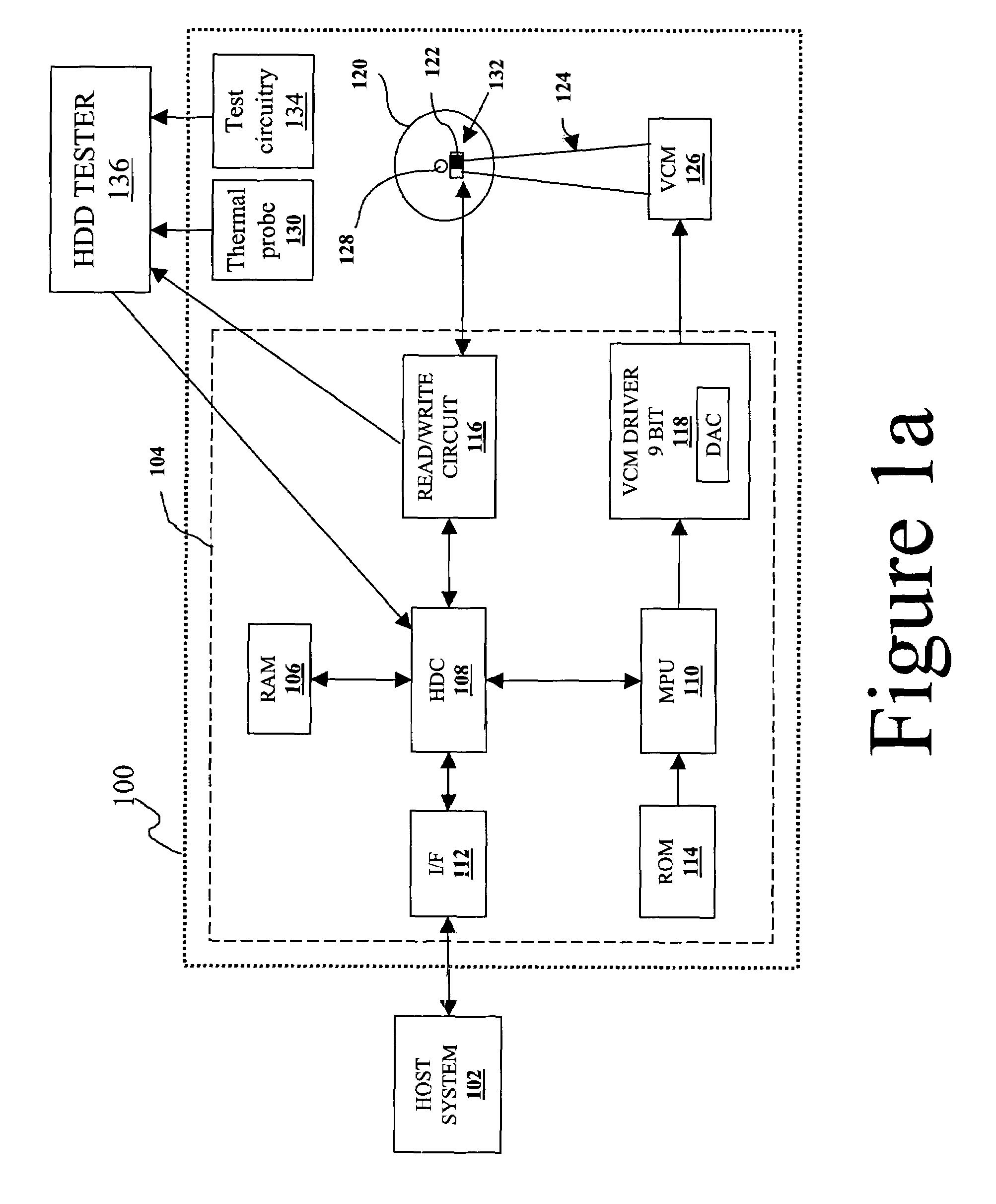
[0024]With reference now to the figures and in particular FIG. 1a, there is depicted a block diagram of a hard disk drive (HDD) 100 as contemplated by the present invention. HDD 100 has a set of hard disks 120, which are rigid platters composed of a substrate and a magnetic medium. Since the substrate is non-magnetic, both sides of each hard disk 120 can be coated with the magnetic medium so that data can be stored on both sides of each hard disk 120.

[0025]An actuator arm 124 moves a slider 132, which is gimbal mounted to the actuator arm 124. The slider 132 carries a magnetic read / write head 122 to a specified lateral position above the surface of the hard disk 120 when a voice coil motor (VCM) 126 swings the actuator arm 124.

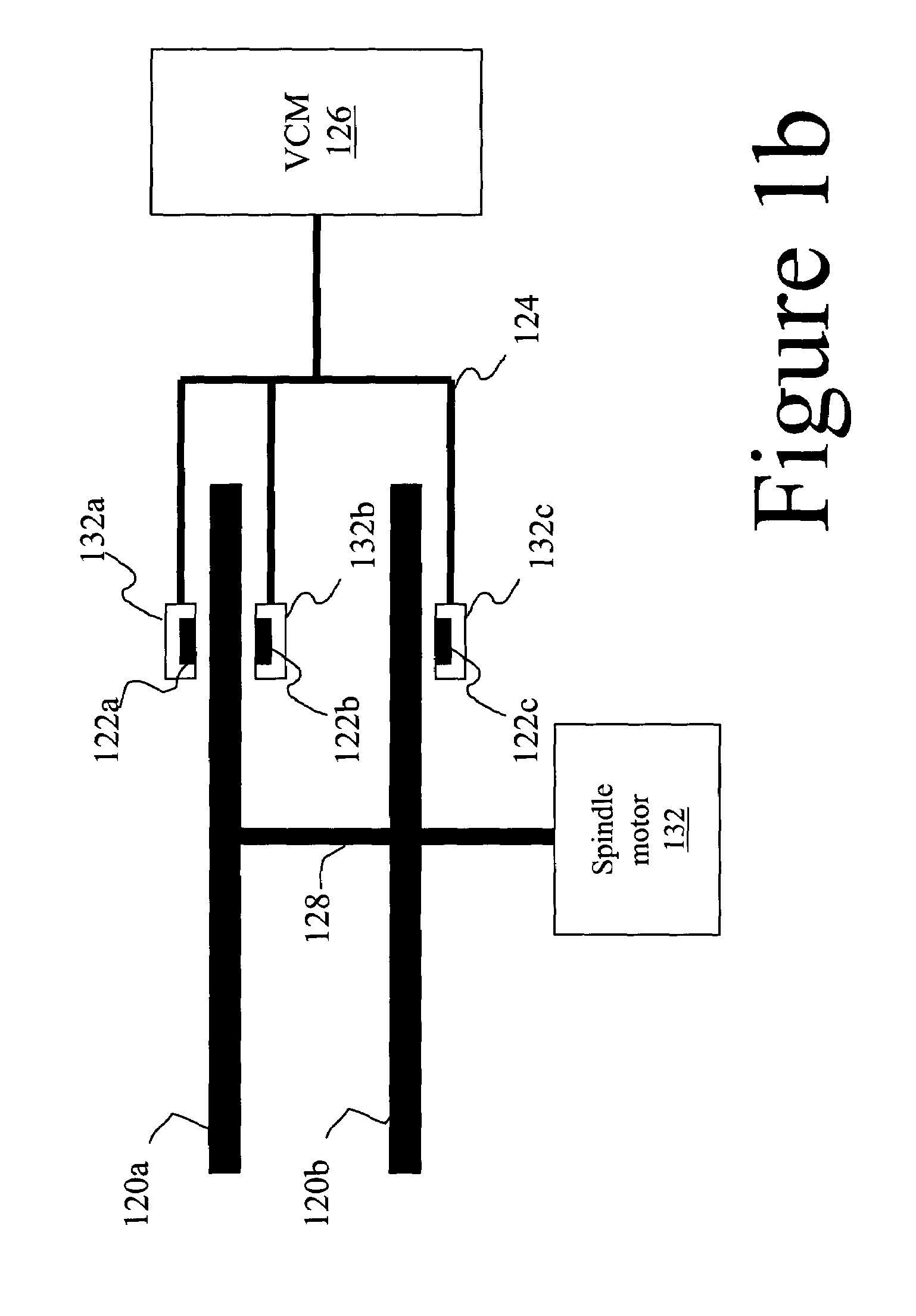
[0026]With reference now to FIG. 1b, there is depicted additional detail of hard disks 120. Hard disks 120 are a stack of hard disk platters, shown in exemplary form as hard disks 120a–b. Preferably, more than two platters are used, but only two are shown for ...


PUM

PropertyMeasurementUnit
drive temperatureaaaaaaaaaa
temperatureaaaaaaaaaa

Abstract

A method and program product supporting adjusting a temperature of a hard disk drive (HDD) during testing. An HDD test program is performed within a pre-determined optimal test temperature range. The HDD is kept within this pre-determined test temperature range by switching HDD operation modes back and forth between a higher heat generating Rapid Seek Mode and a lower heat generating IDLE mode. The HDD is thus kept within the optimal test temperature range without the use of external heating and / or cooling devices.

Description

BACKGROUND OF THE INVENTION[0001]1. Technical Field[0002]The present invention relates in general to storage systems, and in particular disk drives. Still more particularly, the present invention relates to a method for controlling the temperature of a disk drive during testing using the disk drive's own hardware and sensors.[0003]2. Description of the Related Art[0004]A hard disk drive (HDD) is a digital data storage device that writes and reads data via magnetization changes of a magnetic storage disk along concentric tracks. The HDD is tested before being shipped to the customer. In addition, the customer often tests the HDD on a periodic basis after the HDD is operational. The HDD can be tested either for on / off failures or for gradual performance degradation.[0005]On / off failures are failures in which an item fails, such as a cable breaks, a disk does not spin, a read / write head does not function at all, etc. Such failures are easy to identify and locate, but may require puttin...

Claims


Application Information

Patent Timeline
Patent Type & Authority Patents(United States)
IPC IPC(8): G11B15/18G11B15/46G11B21/02G11B5/596G11B5/00G11B5/012G11B25/04G11B27/36G11B33/14
CPCG11B5/012G11B27/36G11B33/144G11B25/043G11B2005/001G11B2220/20
Inventor ESCOBAR, JORGE F.KHURSHUDOV, ANDREI
Owner HITACHI GLOBAL STORAGE TECH NETHERLANDS BV
Learn More