Close range sonar system and method

a sonar system and close range technology, applied in the field of sonar systems, to achieve the effect of minimizing the noise of the first sonar array and the second sonar array, and maximizing the relationship of sonar signals

Inactive Publication Date: 2006-11-21
THE GOVERNMENT OF THE UNITED STATES OF AMERICA AS REPRESENTED BY THE SEC OF THE NAVY NAVAL RES LAB WASHINGTON
View PDF6 Cites 19 Cited by
  • Summary
  • Abstract
  • Description
  • Claims
  • Application Information

AI Technical Summary

Benefits of technology

[0023]In operation of the invention, a method for avoiding a close encounter between an ownship platform and another underwater platform is provided. The method may comprise steps such as, for instance, mounting a first sonar array to a hull of the ownship, receiving acoustic signals from the first sonar array related to the other platform and a first sonar array noise, providing a second sonar array attached to a cable extendable from the ownship, and receiving acoustic signals from the second sonar array related to the other platform and a second sonar array noise.
[0024]Other steps may comprise correlating the acoustic signals received from the first sonar array and the second sonar array to minimize the first sonar array noise and the second sonar array noise while maximizing sonar signals related to other underwater platform. The method may further comprise determining a position of the other platform with respect to the ownship underwater platform for close range operations.

Problems solved by technology

An example of such noise may be ownship noise produced by water flowing past the hull of the submarine.
The second sonar array is also operable for detecting acoustic pressure waves from the other platform but is placed at a distance such that the noise, which may be ownship noise due to the propeller, is uncorrelated from the noise received by the first sonar array.

Method used


Image

  • Close range sonar system and method
  • Close range sonar system and method
  • Close range sonar system and method

Examples


Embodiment Construction

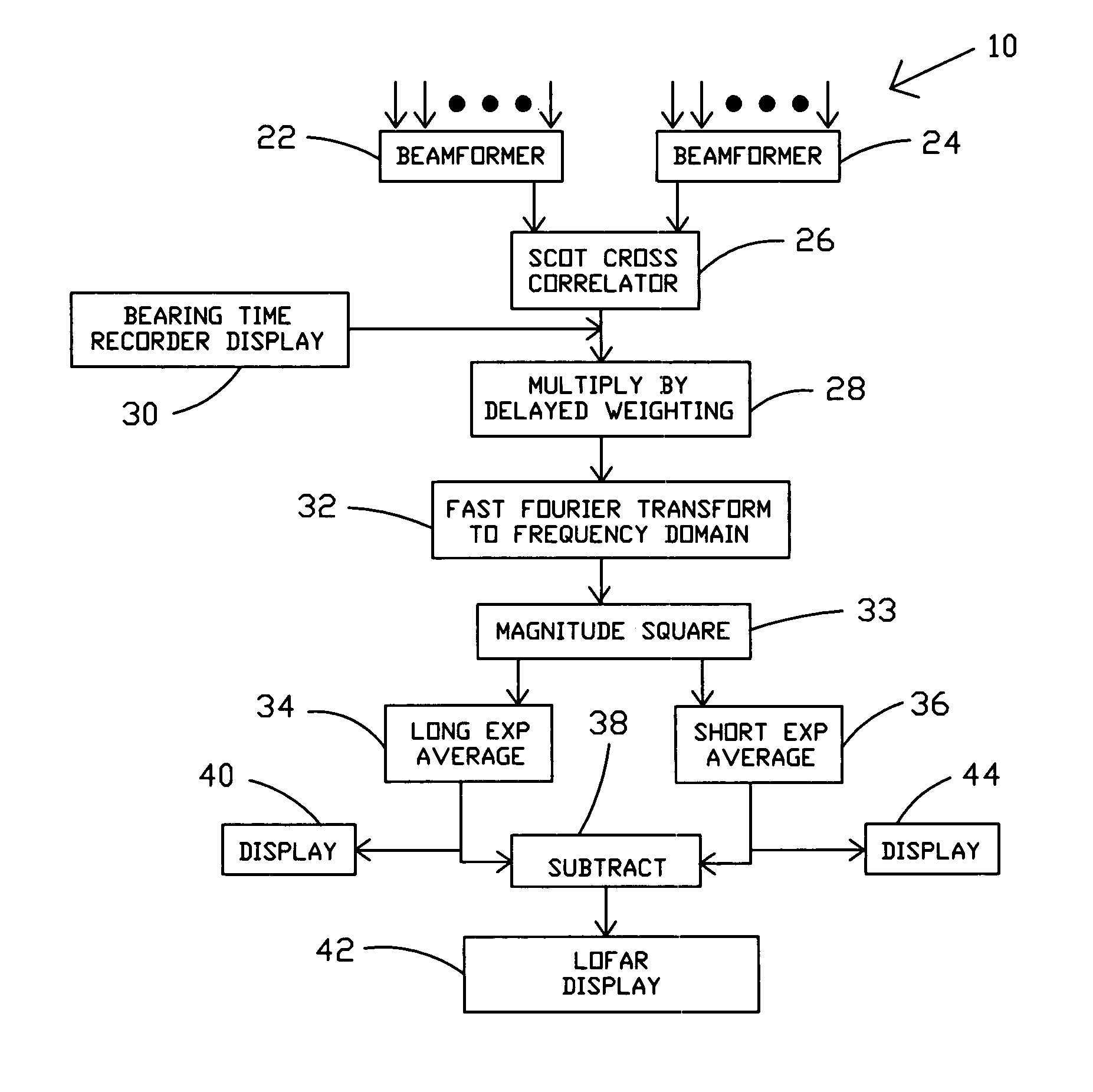
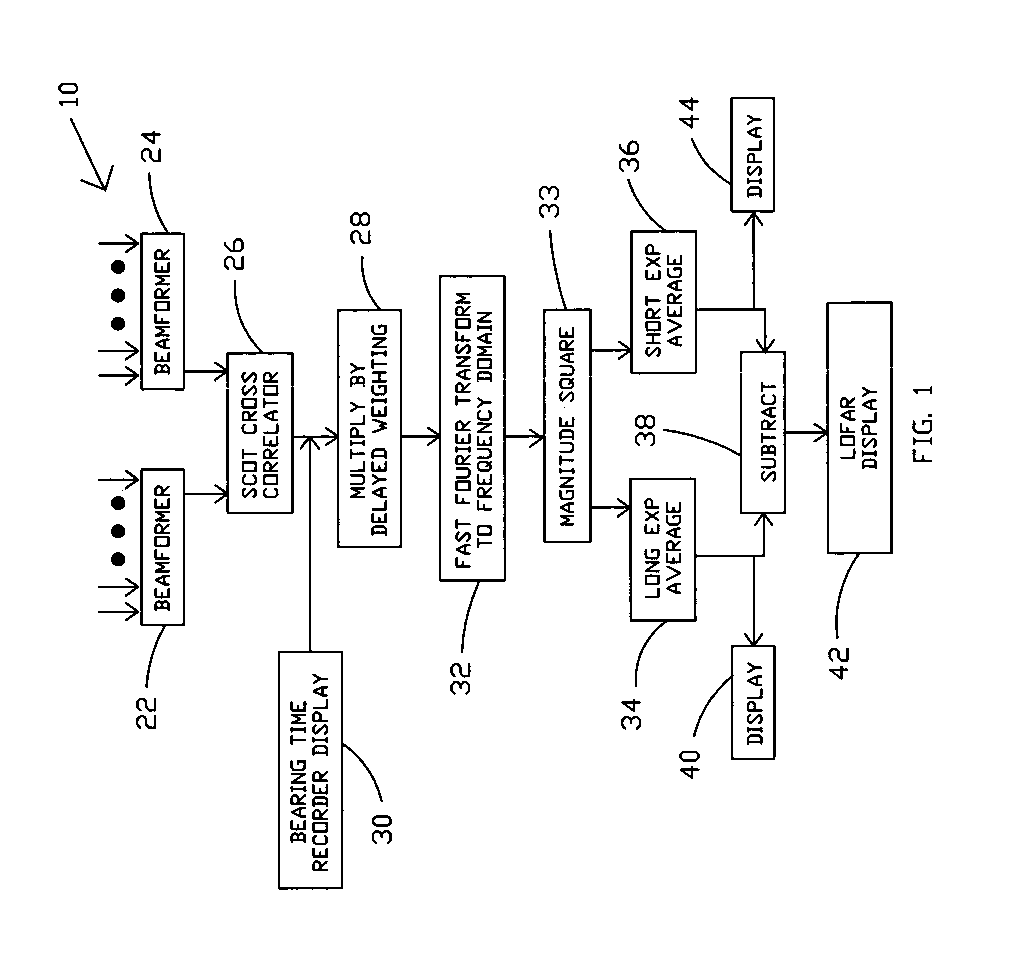
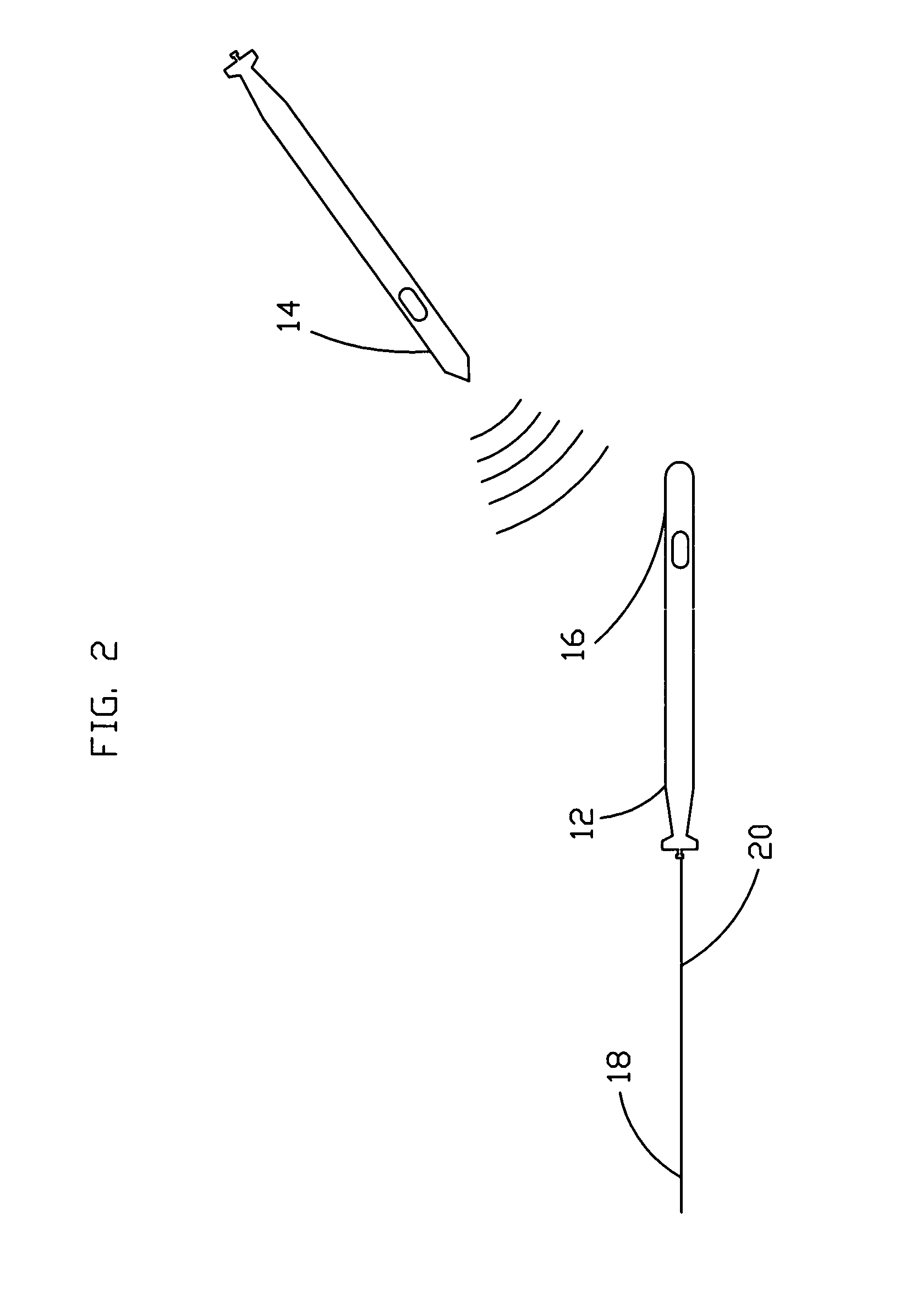
[0028]Referring now to the drawings, and more particularly to FIG. 1, there is shown a block diagram of close range sonar 10 in accord with the present invention which may be utilized in the situation shown in FIG. 2 by submarine 12 to avoid impending close encounter with surface vessel or submarine 14 that is approaching from the generally forward direction.

[0029]In a preferred embodiment, a platform, such as, a surface ship, an unmanned underwater vehicle or a submarine 12 preferably comprises at least two distinct passive sonar arrays which are separated a suitable distance from each other such that the received signals, such as ownship noise, from each sonar array is substantially uncorrelated. Hull sonar array 16 is preferably mounted or embedded over the hull surface of the submarine. Towed sonar passive array 18 may be disposed at a selectable distance from submarine 12 by use of preferably retractable cable 20. By adjusting the length of cable 20, towed array 18 may be provi...


PUM


Abstract

A system for close range sonar is provided. The system provides sufficient warning to permit maneuvering to avoid a close encounter even in the forward starboard/port regions, which have been problematic in the past due to ownship noise. The system utilizes a hull mounted sonar array and a towed sonar array which may be controlled in position to provide sufficient separation of noise received by both sonar arrays such that the noise is largely uncorrelated. The system utilizes beamformers for each array to supply a cross-correlator section which is able to minimize the ownship noise and maximize the signal thereby providing more time for maneuvering. The system also provides a LOFAR display and other displays that are highly sensitive to detecting close encounters.

Description

STATEMENT OF GOVERNMENT INTEREST[0001]The invention described herein may be manufactured and used by or for the Government of the United States of America for governmental purposes without the payment of any royalties thereon or therefore.BACKGROUND OF THE INVENTION[0002](1) Field of the Invention[0003]The present invention relates generally to sonar systems and, more particularly, to a close range sonar system for improved ambiguity resolution and increased heading / bearing resolution for underwater acoustic radiators.[0004](2) Description of the Prior Art[0005]It is highly desirable to accurately and quickly determine the relative positions of acoustic radiators Timely and accurate information becomes important in certain situations.[0006]Presently, the performance of some sonar systems has been determined to be less than optimal due to low signal-to-noise ratio (SNR) and noise problems. For instance, the flow of fluid creates considerable noise which hampers data collection / analys...

Claims


Application Information

Patent Timeline
Patent Type & Authority Patents(United States)
IPC IPC(8): G01S3/80
CPCG01S3/8083G01S5/20
Inventor CARTER, G. CLIFFORDJOHNSON, MARY H.PISTACCHIO, DAVID J.
Owner THE GOVERNMENT OF THE UNITED STATES OF AMERICA AS REPRESENTED BY THE SEC OF THE NAVY NAVAL RES LAB WASHINGTON
Why Eureka
Try Eureka