Transmitter

Inactive Publication Date: 2006-11-21
EHNDRESS KHAUZER GMBKH KO KG
3 Cites 6 Cited by

AI-Extracted Technical Summary

Problems solved by technology

In the processing of the pre-processed raw signals, errors can occur, which remain unrecognized in the case of conventional transmitters.
When using software, pr...

Benefits of technology

[0008]It is an object of the invention to provide a transmitter that per...

Abstract

A transmitter including: a sensor, which serves for registering a physical parameter (X) and transducing such into an electrical quantity; a signal pre-processor, which serves for converting the electrical quantity into a raw signal (R); a signal processor, which serves for converting the raw signal (R) into a measurement signal (M); an output stage, which serves for issuing an output signal corresponding to the measurement signal (M); and a monitoring unit, which in operation compares the output signal with an auxiliary signal (H) derived from the raw signal (R) and triggers a safety-directed adjustment of the output signal, when a difference between the output signal and the auxiliary signal (H) exceeds a predetermined limit.

Application Domain

Electric signal transmission systemsAmplifier modifications to reduce noise influence +5

Technology Topic

EngineeringSignal processing +4

Image

  • Transmitter
  • Transmitter
  • Transmitter

Examples

  • Experimental program(1)

Example

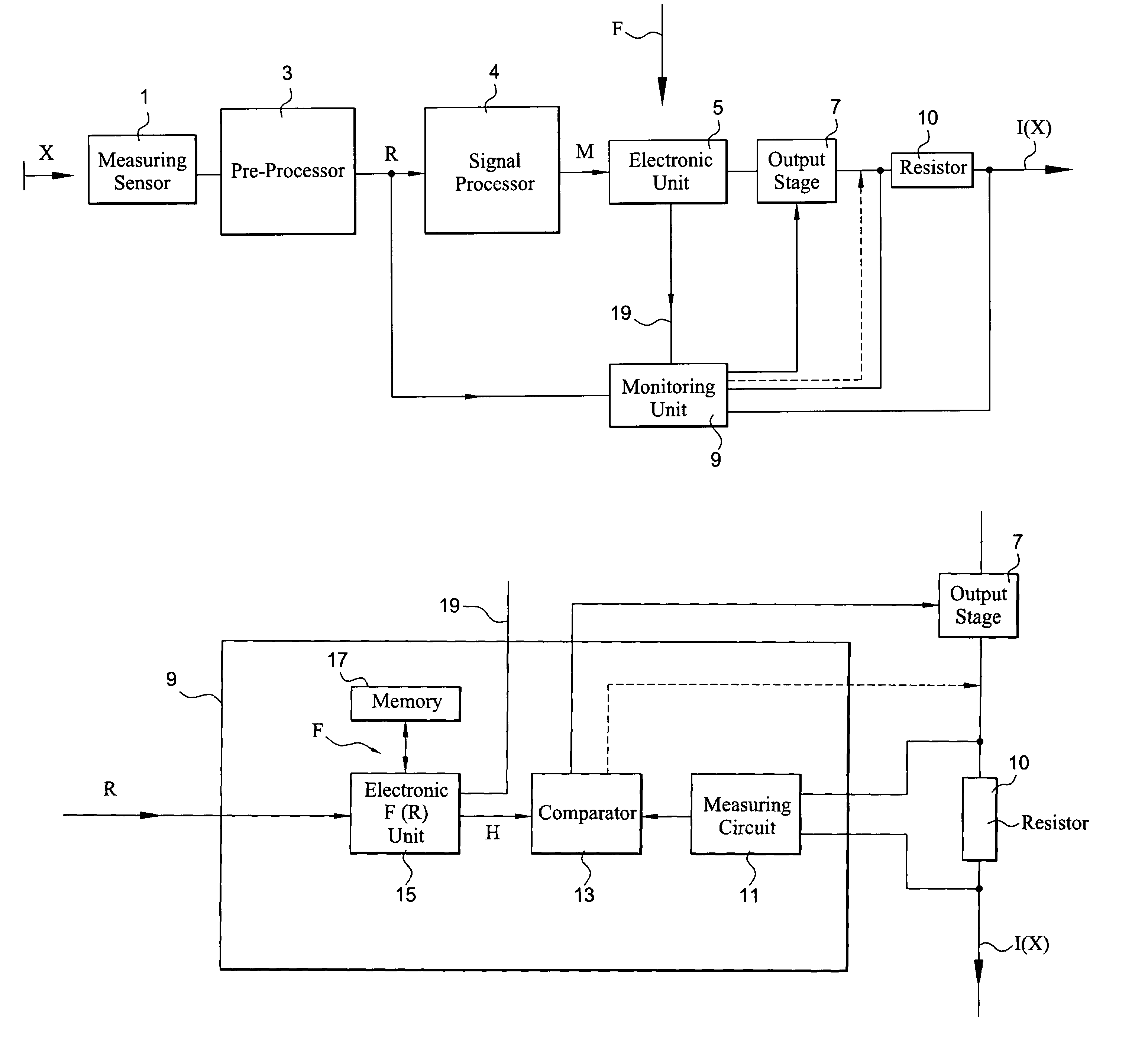
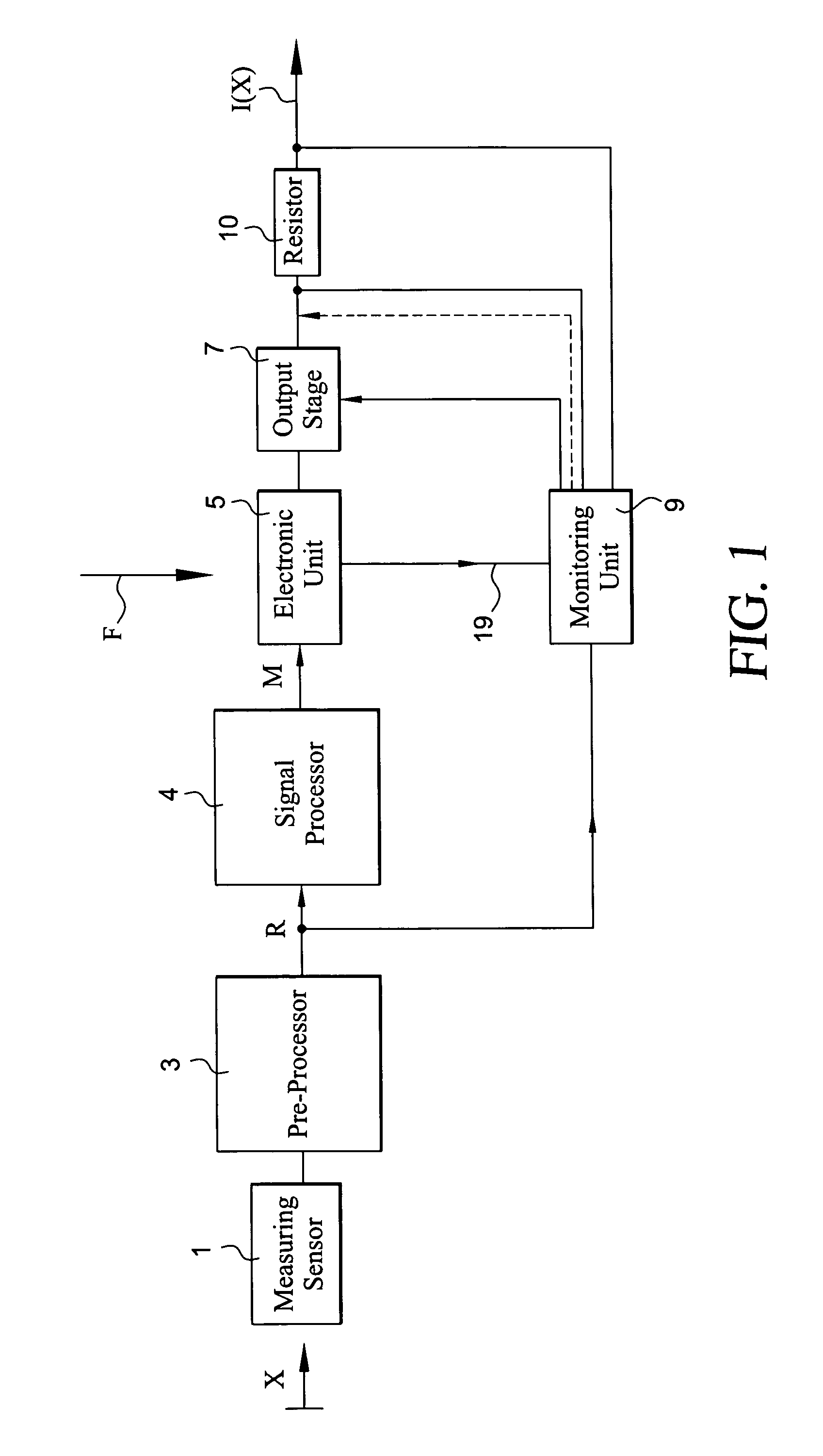
[0029]The transmitter contains a measuring sensor 1, which serves for registering a physical parameter X and transducing such into an electrical quantity. The sensor can be e.g. a pressure-, temperature-, flow-, or fill-level-sensor. The physical parameter X affects the measuring sensor 1, and the sensor, in turn, issues an electrical quantity corresponding to a present, measured value of the physical parameter X. The electrical quantity is fed to a signal pre-processor 3 serving for converting the electrical quantity into a raw signal R, which is available for a further processing and/or evaluation. For this, the electrical quantity is e.g. amplified and/or filtered.
[0030]The raw signal R is converted into a measurement signal M by a following signal processor 4. Here, e.g. compensation of a possible temperature dependence of the raw signal is done. Also, corrections and adjustments resulting from e.g. sensor-specific characteristic curves or compensation- and/or calibration-data can be cared for.
[0031]The measurement signal M is applied to an electronic unit 5, e.g. a microprocessor, which processes the measurement signal M in accordance with an application-specific transfer function F. Here, e.g. a zero-point of the physical quantity desired by the user and a scaling of the measured value, e.g. in the form of a measurement range specification, or the units, in which a result of measurement is to be issued, are cared for.
[0032]The measurement signal processed according to the transfer function F is applied to an output stage 7, which issues an output signal corresponding to the measurement signal M. An output signal can e.g. be a current corresponding to the presently measured value, a voltage corresponding to the presently measured value, or a digital signal. In the illustrated example of an embodiment, the output signal is a current I(X) changing as a function of the physical parameter X.
[0033]A monitoring unit 9 is provided in parallel with the signal processing path formed by the signal processor 4, the electronic unit 5 and the output stage 7. FIG. 2 shows an example of an embodiment for a construction of the monitoring unit 9.
[0034]The monitoring unit 9 has a first input, to which the raw signal R is applied.
[0035]In operation, the monitoring unit 9 compares the output signal with an auxiliary signal H derived from the raw signal R and effects a safety-directed adjustment of the output signal, when a difference between the output signal and the raw signal R exceeds a predetermined level. The raw signal R is naturally less exact than the output signal. For this reason, preferably a tolerable difference between auxiliary signal H and output signal is defined, such as can occur because of the different accuracies of the two signals. If the difference between the two signals exceeds this limit, then a malfunction has occurred, which is immediately recognized by the transmitter embodied according to the invention. Correspondingly, the transmitter can then effect a safety-directed adjustment of the output signal.
[0036]The operator is warned by the transmitter and it is assured that no major damage can be caused, before the error is corrected.
[0037]In the illustrated example of an embodiment using an analog output signal, a resistor 10 is located in the output branch, and the output signal is taken from across the resistance 10 and fed to the monitoring unit. The monitoring unit 9 has a measuring circuit 11, in which the output signal is registered and fed to a comparator 13.
[0038]Preferably, the monitoring unit also has an electronic unit 15, e.g. a second microprocessor, which derives the auxiliary signal H from the raw signal R, by processing the raw signal R according to the application-specific transfer function F. The electronic unit 15 compares the so-won auxiliary signal H with the present output signal.
[0039]In this connection, the electronic unit 15 is assigned a memory 17, in which the transfer function F is stored.
[0040]During start-up of a transmitter of the invention, preferably the transfer function F is fed in a first step by the user via a communication interface to the first electronic unit 5 in the signal processing branch. Alternatively, a transfer function present in the transmitter can also be selected by the user. This can, for example, transpire by way of a menu permitting selection of the different measuring ranges, signal output modes, units in which the measurement is to be given, etc.
[0041]The communication interface is merely symbolically indicated in FIG. 1 by means of an arrow. Although here a communication interface is spoken of, with some transmitters also a simple unidirectional transfer of the transfer function F to the electronic unit 5 can be sufficient. This does not have to happen via a separate interface, it can occur also over the lines that are used to supply the transmitter and/or over those on which the output signal is issued.
[0042]From the first electronic unit 5, the transfer function F is transferred once over a data line 19 from the first to the second electronic unit 5, 15 and stored in a memory 17 assigned to the second electronic unit 15.
[0043]In a transmitter of the invention, the entire signal processing branch is monitored. Any kind of error occurring therein is immediately noticed, and the transmitter reacts automatically in a safety-directed manner.
[0044]This occurs e.g. in that the electronic unit 15 of the monitoring unit 9 effects a corresponding adjustment over the output stage 7. This is indicated in FIGS. 1 and 2 by a continuous line. Alternatively, the monitoring unit 9 can naturally act on the output signal directly. In the case of the described electrical-current output, this could be effected such that the monitoring unit 9 acts on the output signal between the output stage and the resistance 10 so that the output signal assumes the desired safety-directed adjustment. This is shown in the figures by the dashed line.
[0045]A safety-directed adjustment of the output signal can e.g. be an alarm signal. In the described analog current output, an alarm signal can e.g. be the regulating of the current to a value which it does not assume under normal measurement conditions. If the currents for the measurement existing at the time lie between 4 mA and 20 mA in error-free operation, then currents above 20 mA, respectively below 4 mA, can have the meaning of an alarm.
[0046]Alternatively, a safety-directed adjustment can, naturally, also mean that an output signal is set, which corresponds to a measured value at which the least possible damage is triggered by the malfunctioning transmitter. For example, in the case of a fill level measurement, a safety-directed adjustment can mean that the transmitter, which has recognized its malfunction, reports, independently of the actual fill level, that the container is full, in order that no more fill substance be introduced into the container. In this way, an overflow of the container is prevented. Additionally to this adjustment, an alarm signal is advantageously superimposed on the output signal.

PUM

no PUM

Description & Claims & Application Information

We can also present the details of the Description, Claims and Application information to help users get a comprehensive understanding of the technical details of the patent, such as background art, summary of invention, brief description of drawings, description of embodiments, and other original content. On the other hand, users can also determine the specific scope of protection of the technology through the list of claims; as well as understand the changes in the life cycle of the technology with the presentation of the patent timeline. Login to view more.
Why Eureka
Try Eureka