
Fly-by-wire limp home and multi-plex system

a technology of multi-plex system and fly-by-wire, which is applied in the direction of mechanical equipment, transportation and packaging, and gearing, etc., can solve the problem of not providing skip shifting

Active Publication Date: 2006-11-28
GM GLOBAL TECH OPERATIONS LLC
View PDF11 Cites 42 Cited by
  • Summary
  • Abstract
  • Description
  • Claims
  • Application Information

AI Technical Summary

Problems solved by technology

The above-identified Long et al. patent does not provide for skip shifting.

Method used


Image

  • Fly-by-wire limp home and multi-plex system
  • Fly-by-wire limp home and multi-plex system
  • Fly-by-wire limp home and multi-plex system

Examples


Embodiment Construction

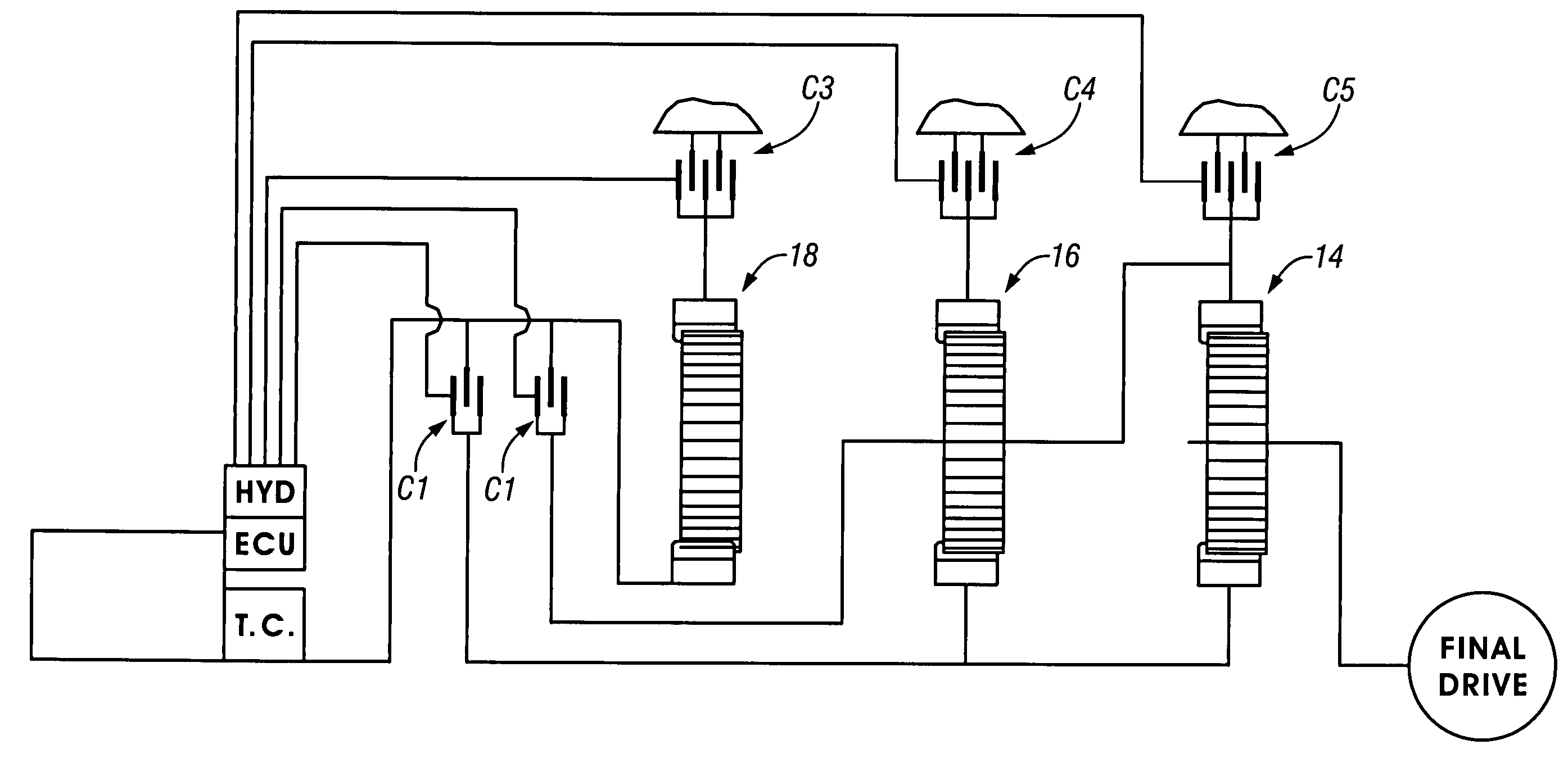
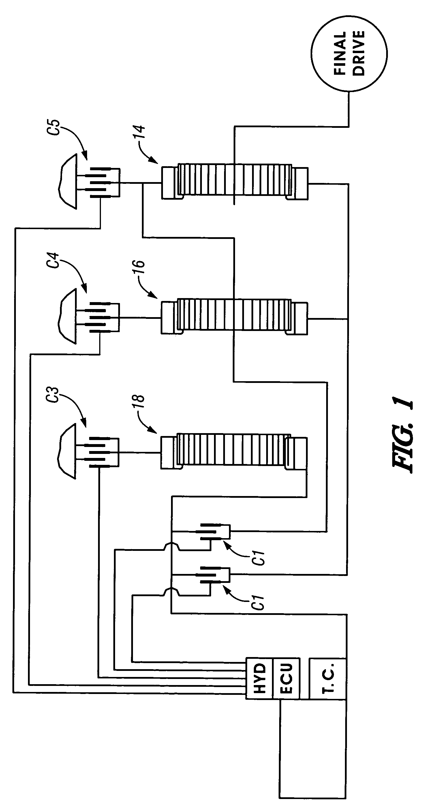
[0022]A power transmission shown in FIG. 1 includes an engine and torque converter (TC), an input shaft 10, an output shaft 12, and three planetary gearsets 14, 16, and 18. The planetary gearsets 14, 16, and 18 are controlled to provide six forward speed ratios, a reverse speed ratio, and a neutral condition between the input shaft 10 and the output shaft 12. These conditions are provided by five torque-transmitting mechanisms C1, C2, C3, C4, and C5. The torque-transmitting mechanisms C1 and C2 are rotating-type torque-transmitting mechanisms commonly termed clutches, and the torque-transmitting mechanisms C3, C4, and C5 are stationary-type torque-transmitting mechanisms commonly termed reaction clutches or brakes.

[0023]To establish a reverse ratio, the torque-transmitting mechanisms C3 and C5 are engaged. In the neutral condition, the torque-transmitting mechanism C5 is engaged. During the neutral to first ratio interchange, the solenoid is activated to place the logic valve 30 in ...


PUM


Abstract

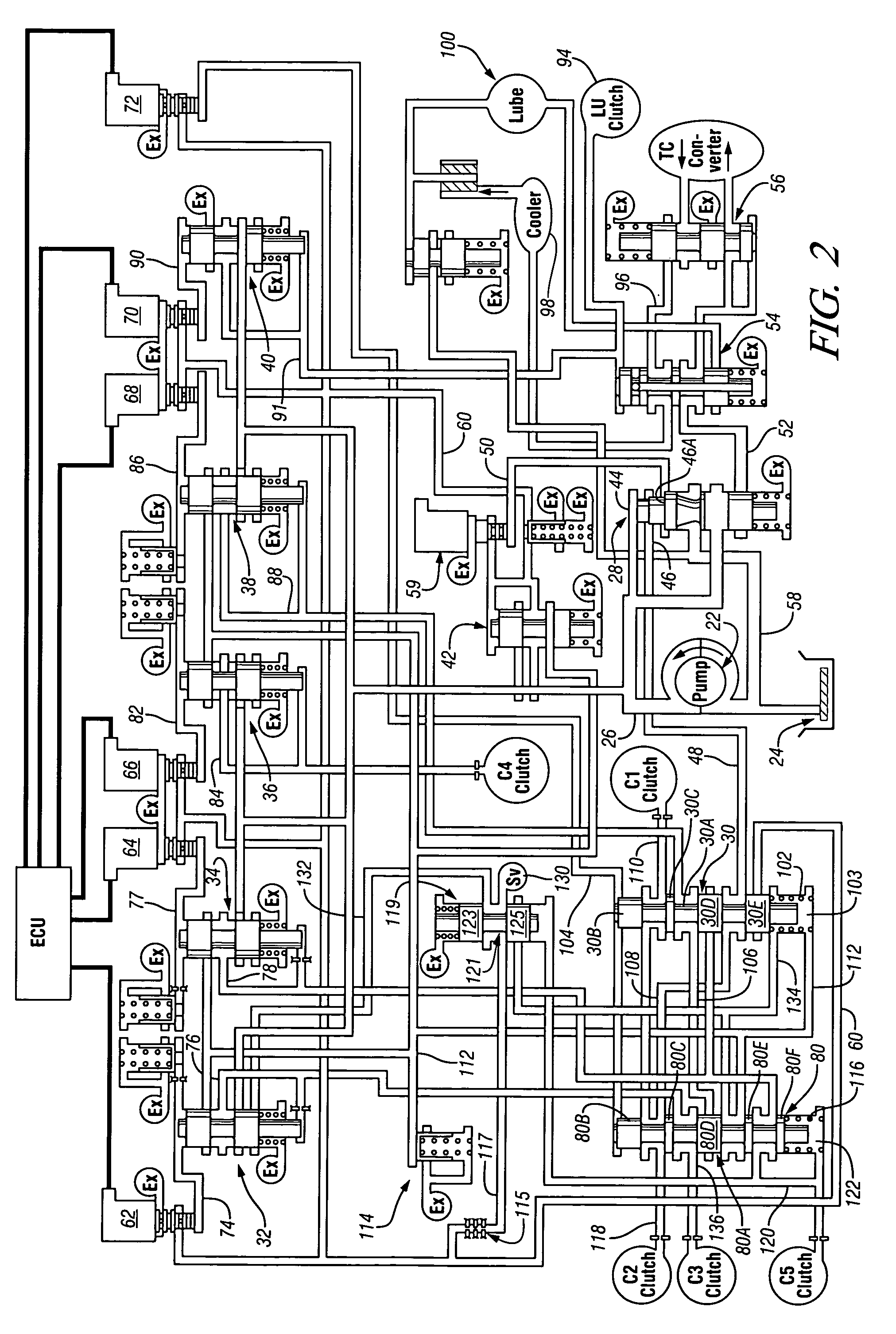
An electro-hydraulic control mechanism for use with a multi-speed transmission includes a pair of logic valves, which are manipulated during the ratio interchanges and the ratio establishment by aiding in the distribution of fluid pressure from a plurality of trim valves. The logic valves are retained in specific drive ranges in the event of electrical discontinuance.

Description

TECHNICAL FIELD[0001]This invention relates to electro-hydraulic controls for transmissions, and more particularly, to controls having electronic mechanisms.BACKGROUND OF THE INVENTION[0002]Many of the currently-available high performance planetary transmissions employ what is termed clutch-to-clutch shifting. This term indicates that the ratio change is performed by disengaging one disc-type friction device while engaging another disc-type friction device. This is accomplished without the use of one-way devices. Therefore, the overlap control needs to be quite accurate in these situations and the position of the control must also be accurate.[0003]At least one planetary transmission that is utilized with clutch-to-clutch shifting controls is shown in U.S. Pat. No. 4,070,927 issued to Polak on Jan. 31, 1978. This transmission has a control that is equipped with solenoid controlled trim valves that are actuated by electronic control units to provide engagement and disengagement press...

Claims


Application Information

Patent Timeline
Patent Type & Authority Patents(United States)
IPC IPC(8): F16H31/00
CPCF16H61/12F16H61/0206F16H61/686F16H2061/1232F16H2200/0052F16H2200/201F16H2061/1268F16H2061/1292
Inventor LONG, CHARLES F.MC CAULEY, PHILLIP F.WEBER, DARREN J.
Owner GM GLOBAL TECH OPERATIONS LLC
Learn More