Method for monitoring the operation of an aircraft piloting device and an aircraft piloting device thus monitored

Inactive Publication Date: 2015-04-23
RATIER FIGEAC
View PDF19 Cites 17 Cited by
  • Summary
  • Abstract
  • Description
  • Claims
  • Application Information

AI Technical Summary

Benefits of technology

[0010]Therefore, the object of the invention is to overcome these disadvantages by proposing a method for monitoring operation, which is highly resilient to a generic malfunction, totally independently of the piloting members t

Problems solved by technology

Such a solution, which is conventional in principle, is heavy, complex and costly to implement and to operate.
Furthermore, it remains imperfect insofar as certain malfunctions that are likely to occur on such a monitoring computer or that si

Method used


Image

  • Method for monitoring the operation of an aircraft piloting device and an aircraft piloting device thus monitored
  • Method for monitoring the operation of an aircraft piloting device and an aircraft piloting device thus monitored
  • Method for monitoring the operation of an aircraft piloting device and an aircraft piloting device thus monitored

Examples


Embodiment Construction

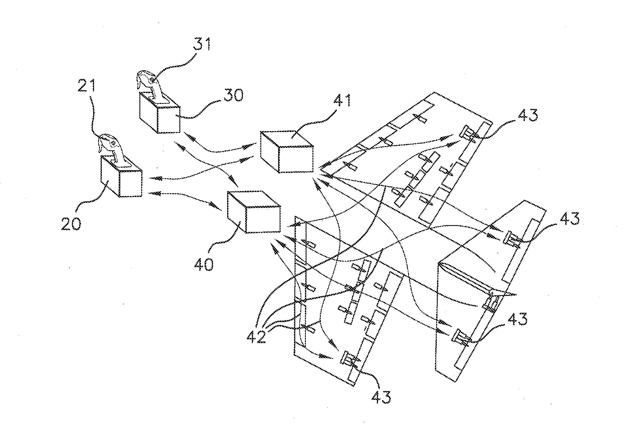
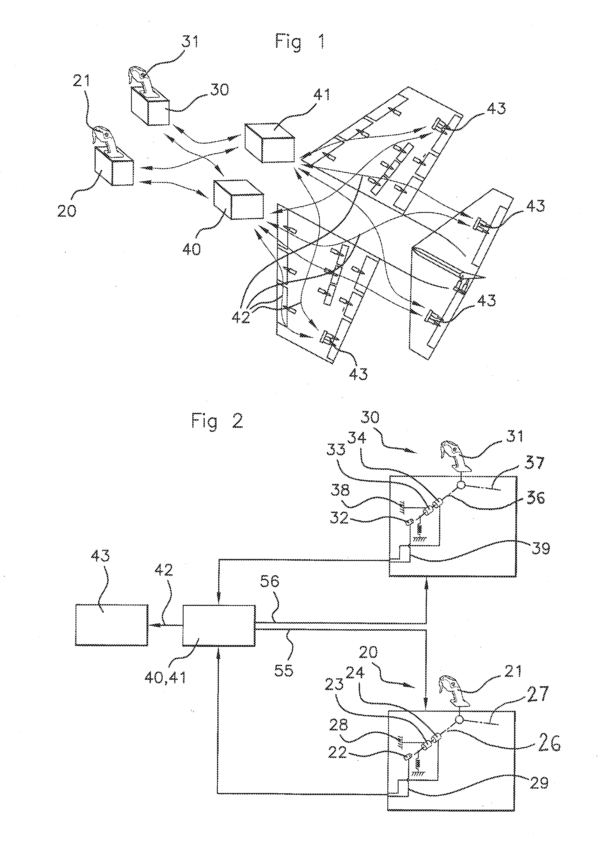
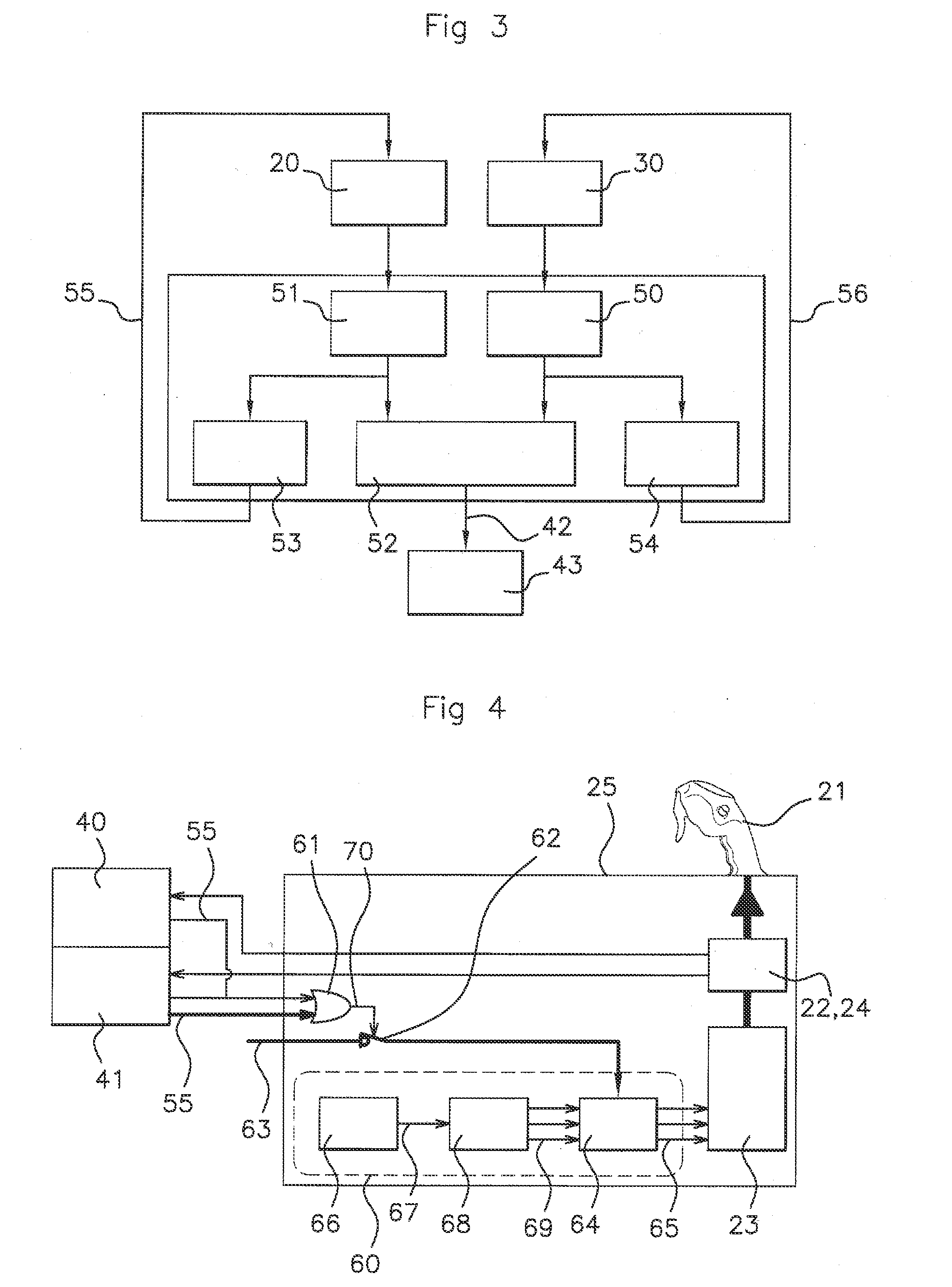
[0056]A piloting device according to the invention, as shown in FIG. 1, comprises, in the example, two piloting members 20, 30 allowing an airplane to be piloted by pitch and by roll, each made up of a mini-flight stick supported by an electromechanical unit 25, allowing the mechanical control and the movement of each mini-flight stick by rotation about a pitch axis 26, 36, respectively, and a roll axis 27, 37, respectively. These mini-flight sticks each comprise a control stick 21 (31, respectively), with each control stick being adapted to be handled by a pilot (and a co-pilot, respectively). These control sticks are mounted and guided rotationally relative to the frame 28, 38, respectively, of the unit, along the two axes 26, 27, 36, 37, respectively, that are orthogonal and generally at least substantially intersecting (forming a link with a central point).

[0057]In this embodiment of the piloting device, the exerted forces are forces that relate to a rotation and the term “torqu...


PUM


Abstract

A method for monitoring an aircraft piloting device including at least one piloting member (20, 30) and at least one fly-by-wire flight control system (40, 41). At least one monitoring module is integrated into this control system and is adapted to compute, on the basis of primary signals processed by sensors associated with at least one piloting member, at least one theoretical value of at least one monitored parameter of at least one piloting member, to compare each theoretical value with measurement signals of each monitored parameter and to select a monitoring action, particularly to generate monitoring signals (55, 56), as a function of the difference between each theoretical value and the measurement signals.

Description

FIELD OF THE INVENTION[0001]The invention relates to a method for monitoring the operation of an aircraft piloting device, to an aircraft piloting device thus monitored and to an aircraft provided with said piloting device.[0002]Throughout the remainder of the document, the term “piloting” and its derivatives refer, unless otherwise stated, to the flying of an aircraft by at least one human pilot operating at least one piloting member such as a flight stick, a control lever, a rudder bar, a pedal, etc. linked to at least one flight control member, such as a control surface or an engine of the aircraft. The term “flight control member” refers to any member for which the position or the state affects the flight of the aircraft: it can particularly relate to control surfaces, engines, the blades of a rotor, etc. The term “control” and its derivatives in aeronautics conventionally refer to the fact of providing a device with signals that bring about a predetermined action of said device...

Claims


Application Information

Patent Timeline
IPC IPC(8): B64C13/10B64C13/12B64C13/50
CPCB64C13/10B64C13/12B64C13/503B64C13/0421B64C13/505B64C13/507G05B23/0235G05B2219/2637B64C13/00G05D1/00
Inventor ANTRAYGUE, CEDRIC
Owner RATIER FIGEAC
Why Eureka
Try Eureka