

Battery protection circuit for simulating an overcurrent condition based on battery current flow
a protection circuit and current flow technology, applied in safety/protection circuits, electrochemical generators, transportation and packaging, etc., can solve problems such as affecting the reliability of the overall system, affecting the performance of rechargeable batteries, and becoming too high for a particular application
- Summary
- Abstract
- Description
- Claims
- Application Information
AI Technical Summary
Benefits of technology
Problems solved by technology
Method used
Image

Examples
Embodiment Construction
[0013]A preferred embodiment of the invention is now described in detail. Referring to the drawings, like numbers indicate like parts throughout the views. As used in the description herein and throughout the claims, the following terms take the meanings explicitly associated herein, unless the context clearly dictates otherwise: the meaning of “a,”“an,” and “the” includes plural reference, the meaning of “in” includes “in” and “on.”
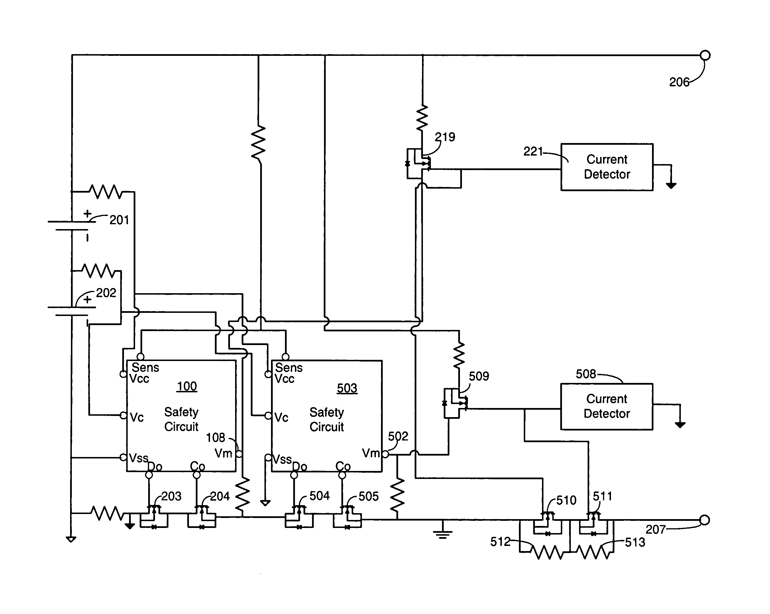
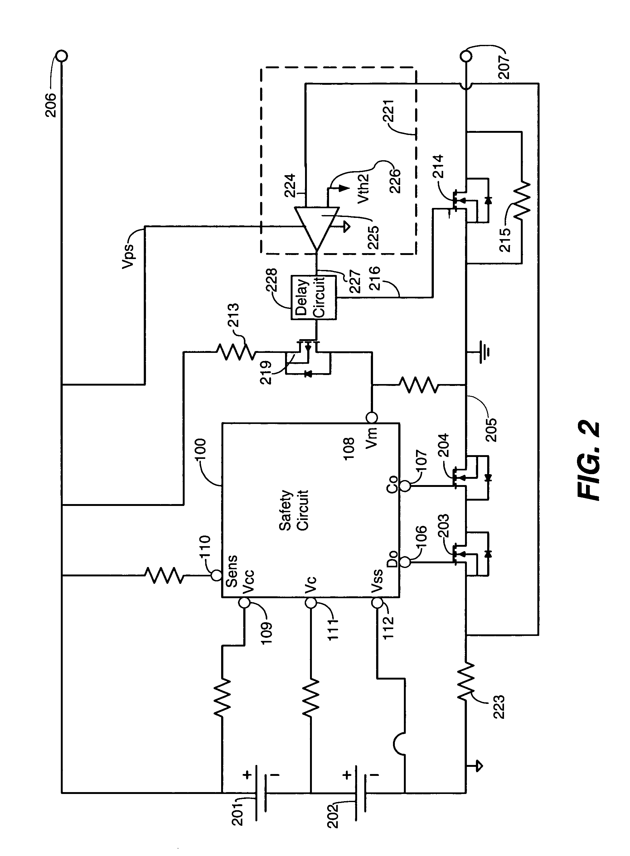
[0014]Copending, commonly assigned application Ser. No. 10 / 737,021, entitled “Power Fault Battery Protection Circuit”, filed Dec. 16, 2003, which is included herein by reference, teaches a circuit that simulates an overcurrent condition in a battery safety circuit when power being delivered to or from a rechargeable cell exceeds a predetermined threshold, like 9 watts for example. This circuit prevents current flow to or from the battery when this threshold is exceeded, with the goal of preventing the overall battery pack from overheating.
[0015]Similarly...
PUM
| Property | Measurement | Unit |
|---|---|---|
| impedance | aaaaa | aaaaa |
| power | aaaaa | aaaaa |
| impedance | aaaaa | aaaaa |
Abstract
Description
Claims
Application Information