Filter assembly with vented filter element

a technology of filter element and assembly, which is applied in the direction of filtration separation, machines/engines, and separation processes, etc., can solve the problems of affecting the performance of downstream components, requiring additional valves, seals, plumbing and/or relatively complex components in order to function properly, and causing erratic fuel delivery. , to achieve the effect of reducing the risk of clogging, simple design, and low cos

Active Publication Date: 2006-12-12
PARKER INTANGIBLES LLC
View PDF16 Cites 68 Cited by
  • Summary
  • Abstract
  • Description
  • Claims
  • Application Information

AI Technical Summary

Benefits of technology

[0008]The present invention provides a novel and unique filter assembly and element for fluid applications which require a purging of air, and has a simple, low cost design. The drain path for the vented air is provided centrally through the element, and more particularly, through a separate and independent fluid channel preferably formed integral with a central support core for the element. The fluid channel directs air from a vent orifice in an upper end cap of the filter element—to a drain path through a central standpipe or otherwise through the lower end of the housing to a drain port. The vent orifice is integral with the element, and is thereby replaced when the element is replaced to reduce the risk of clogging.
[0013]As such, the filter assembly and element described above provide a novel and unique filter assembly and element for fluid applications which require a purging of air, which has a simple, low cost design. The element has an integral vent orifice which is replaced when the element is replaced to reduce the risk of clogging.

Problems solved by technology

The air can create erratic fuel delivery, and effect performance of the downstream components.
While the above solutions have received some acceptance in the market, they generally require additional valves, seals, plumbing and / or relatively complex components in order to function properly.
This can increase the cost of the assembly, and can also add size and weight.

Method used


Image

  • Filter assembly with vented filter element
  • Filter assembly with vented filter element
  • Filter assembly with vented filter element

Examples


Embodiment Construction

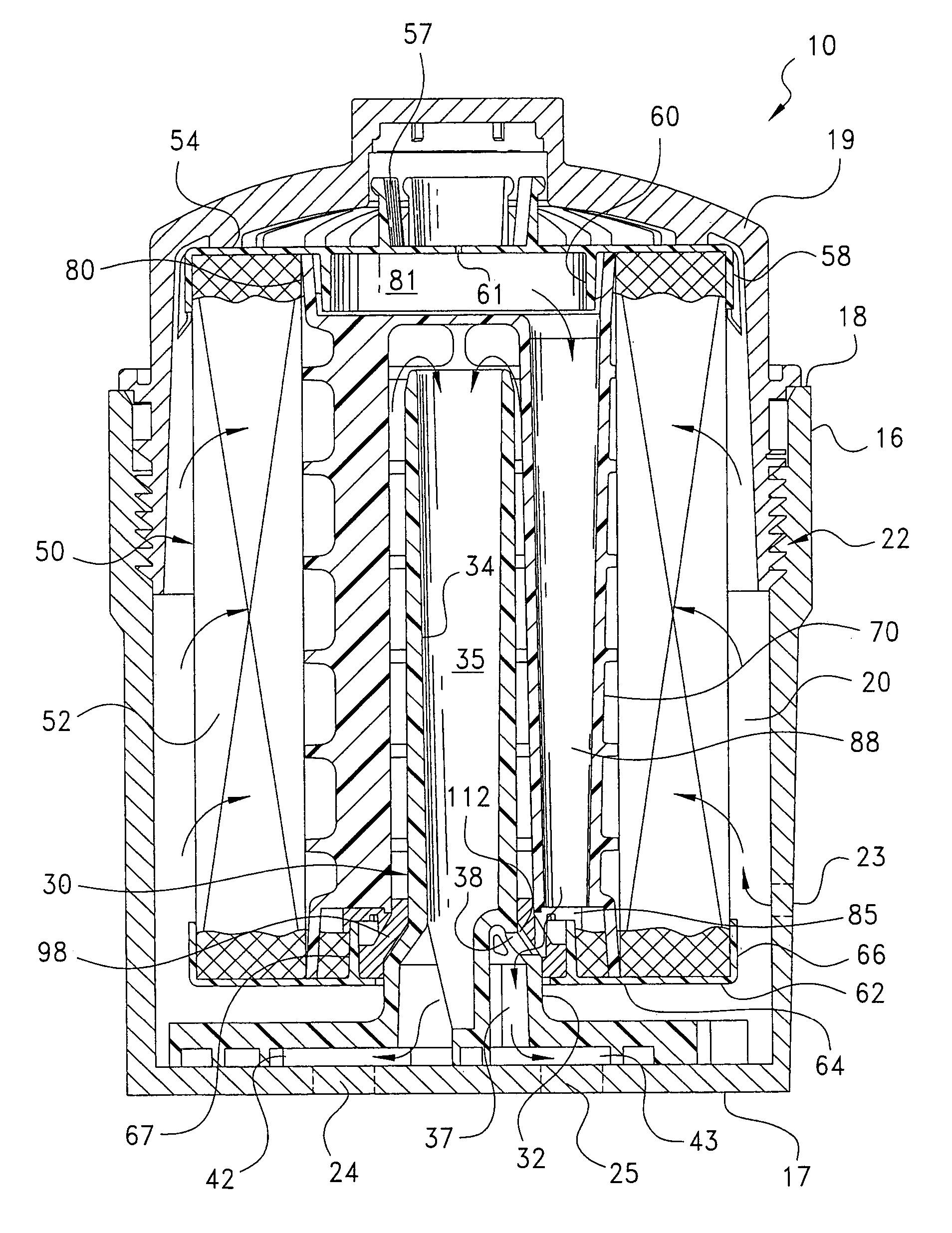
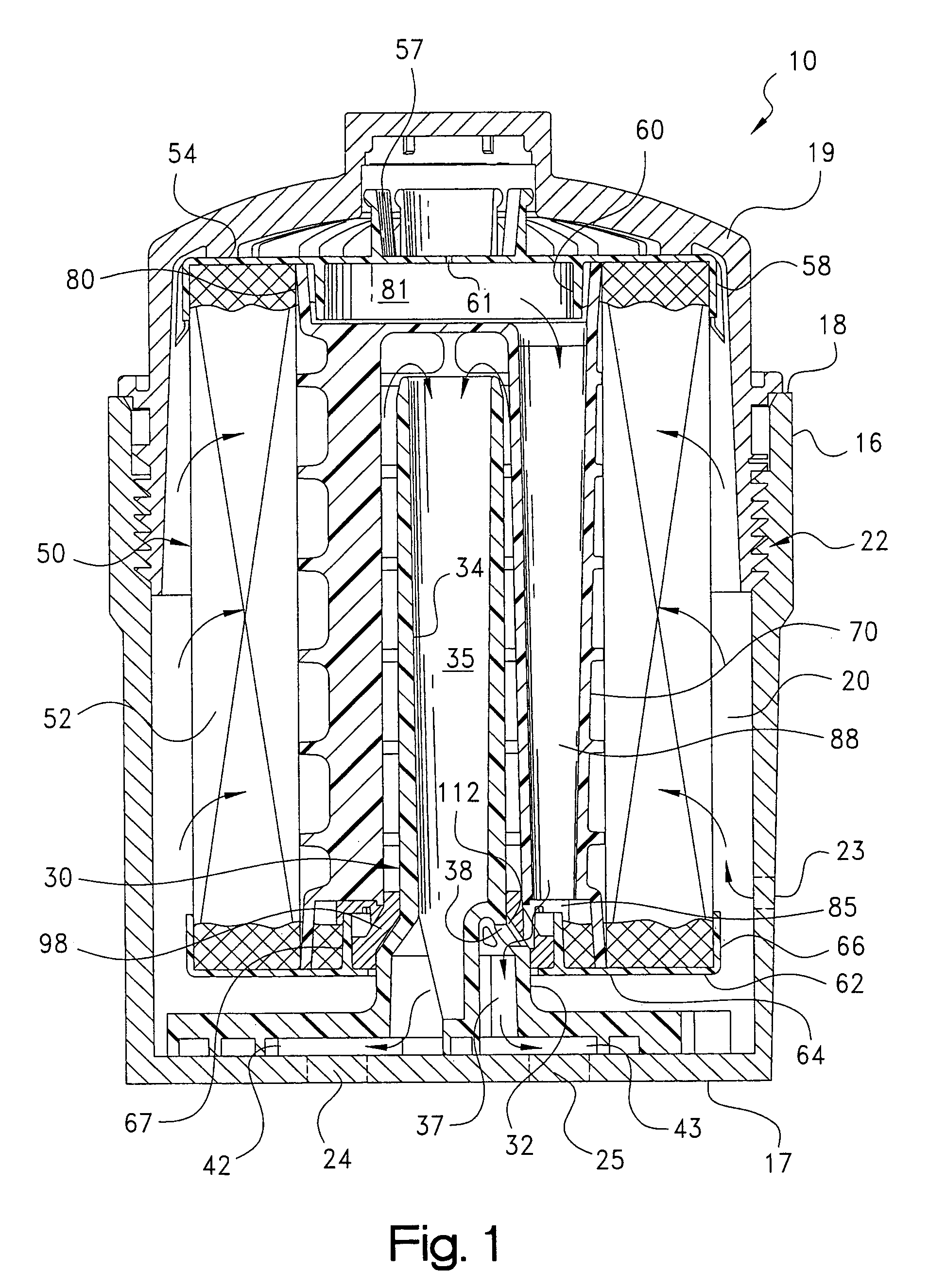
[0020]Referring to the drawings, and initially to FIG. 1, a filter assembly constructed according to the principles of the present invention is indicated generally at 10. The filter assembly 10 can be useful for removing particulate and other contaminants from a fluid system, and in one application, is particularly useful as a filter assembly for removing particulate and other contaminant from a fuel stream in a fuel system for a vehicle. In such an application, the filter assembly can be located downstream, on the pressure side of a pump for moving fuel through the system, e.g., from the tank to the engine. Although it should be note that this is only one appropriate location for the filter assembly, and that other locations and applications are possible.

[0021]The filter assembly 10 includes a housing comprising a cylindrical canister 16 having a lower, closed end 17 and an upper, open end 18. A cup-shaped cover 19 is attached to the open end of the canister, and defines an interna...


PUM

PropertyMeasurementUnit
diameteraaaaaaaaaa
diameteraaaaaaaaaa
inner dimensionaaaaaaaaaa

Abstract

A filter assembly includes a housing with a central standpipe, and cover for enclosing a filter element. The filter element includes a ring of filtration media and first and second end caps. A vent orifice is formed in the first end cap into the central cavity of the media ring. A support core is disposed centrally in the media ring and extends between the first and second end caps. The core includes a separate and independent fluid channel extending from the first end cap that is fluidly connected with the vent orifice, to the second end cap. The second end cap has a central opening, and an annular sealing device bounding the opening which receives and seals to the standpipe and includes through-passages fluidly interconnecting the fluid channel in the core with flow opening(s) along the standpipe or in the lower end of the housing to a drain port.

Description

CROSS-REFERENCE TO RELATED CASES[0001]The present application claims the benefit of the filing date of U.S. Provisional Application Ser. No. 60 / 492,196; filed Aug. 1, 2003, the disclosure of which is expressly incorporated herein by reference.FIELD OF THE INVENTION[0002]The present invention relates generally to fluid filters and assemblies, and more particularly to a fuel filter and assembly for a vehicle fuel system.BACKGROUND OF THE INVENTION[0003]In certain fuel systems, such as for vehicles, a pump is provided to move fuel through the system such as from the tank to the engine. A filter element is sometimes provided downstream (on the pressure side) of the pump to protect downstream components. At start-up and during operation of the system, air can be pushed into the filter housing. It is desirable to vent the accumulated air in the housing to avoid the air being pushed through the element. The air can create erratic fuel delivery, and effect performance of the downstream comp...

Claims


Application Information

Patent Timeline
Patent Type & Authority Patents(United States)
IPC IPC(8): B01D35/28B01D29/21B01D35/01B01D36/00F02M37/22
CPCB01D29/21B01D36/001F02M37/22B01D2201/0415B01D2201/305B01D2201/316F02M37/42F02M37/54B01D29/13B01D36/00
Inventor CLAUSEN, MICHAEL D.JENSEN, RUSSELL D.
Owner PARKER INTANGIBLES LLC
Why Eureka
Try Eureka