Lighting controllers

a controller and light technology, applied in the field of light controllers, can solve the problems of high conductivity, high conductivity, and always greater dc output voltage than dc input voltag

Inactive Publication Date: 2012-09-18
POWER INTEGRATIONS INC
View PDF10 Cites 0 Cited by
  • Summary
  • Abstract
  • Description
  • Claims
  • Application Information

AI Technical Summary

Benefits of technology

[0007]In embodiments the above-described arrangement enables a simple, low-cost design with a single high-voltage switching device whilst at the same time providing a high power factor and, in embodiments, a substantially continuous input current. Thus in some particularly preferred embodiments the SEPIC converter includes an active switch which also serves as one of the switches for the pair of inductive elements of the push-pull output stage. In some embodiments the other of the switches for the pair of inductive elements is provided by a passive element, more particularly a diode; in other embodiments a second active switch, preferably also shared with the SEPIC converter, is employed. This latter arrangement facilitates variation of the duty cycle of the SEPIC converter above 0.5, for example substantially over the range 0 to 1, enabling the dc output voltage of the SEPIC conductor to be greater or less that the dc output voltage. In embodiments the active switch comprises the transistor; in some particularly preferred embodiments a bipolar transistor although a MOS switching device may also be employed.
[0008]In embodiments the active switch of the SEPIC converter is coupled by a rectifier to one of the pair of inductive elements, to restrict current flow from a switched node of the SEPIC converter directly to the push-pull output stage inductors. In some particularly preferred embodiments a further rectifier is included between the active switch of the SEPIC converter and a coupling capacitor (in series between the dc input and the dc output of the SEPIC converter), to restrict current flow back from the push-pull output stage to the switched node and then on through the coupling capacitor.
[0015]The low value of the coupling capacitor relative to the storage (output) capacitor helps to reduce a surge in input current (which stresses the components) when the lamp is first switched on. Preferably the capacitance of the coupling capacitor is less than 1 / 10 that of the storage capacitor.
[0016]In some preferred embodiments the controllable active switch has a control terminal (for example a gate or base terminal of a MOS or bipolar switching transistor) which is configured for ground-referenced control. Thus where the switching device comprises a transistor one terminal of the transistor, for example an emitter or source terminal, is at or close to ground potential. This facilitates driving the active switch.

Problems solved by technology

This describes a standard circuit of a ballast for fluorescent lamps comprising a boost converter followed by a half bridge, one of the disadvantages of the boost converter being that the dc output voltage is always greater than the dc input voltage.
However this arrangement is relatively complex.
However this configuration has the disadvantage that, because of the flyback configuration, the input current waveform is discontinuous and hence the conducted emissions are high.

Method used


Image

  • Lighting controllers
  • Lighting controllers
  • Lighting controllers

Examples


second embodiment

[0043]Referring now to FIG. 2, this shows a lighting controller (electronic ballast) 200 illustrating a first variant of the arrangement of FIG. 1. In the circuit of FIG. 2 the push-pull output stage has an additional pair of push-pull inductors, Lpushpull3202 and Lpushpull4204. This arrangement effectively taps the push-pull inductors of FIG. 1a and may be used, for example, if the ac output voltage is undesirably high (although the output voltage is adjustable it is generally preferable to design a circuit so that the output voltage is broadly in the desired range). Providing push-pull output inductors with one or more additional taps increases the flexibility of the design.

[0044]FIG. 3 shows a third embodiment 300 of electronic ballast in which the push-pull output stage employs a transformer secondary for coupling to the lamp, Lpushpull3.

[0045]FIG. 4 shows a fourth embodiment 400 of an electronic ballast including a transformer secondary as illustrated in FIG. 3, and configured ...

embodiment 500

[0046]FIG. 5 shows a further embodiment 500 of the lamp controller (electronic ballast) employing multiple transformer secondaries 502a, 502b each configured to drive one or more lamps. The skilled person will understand that the polarity of the secondary winding is not important in the arrangement of FIG. 3, 4 or 5.

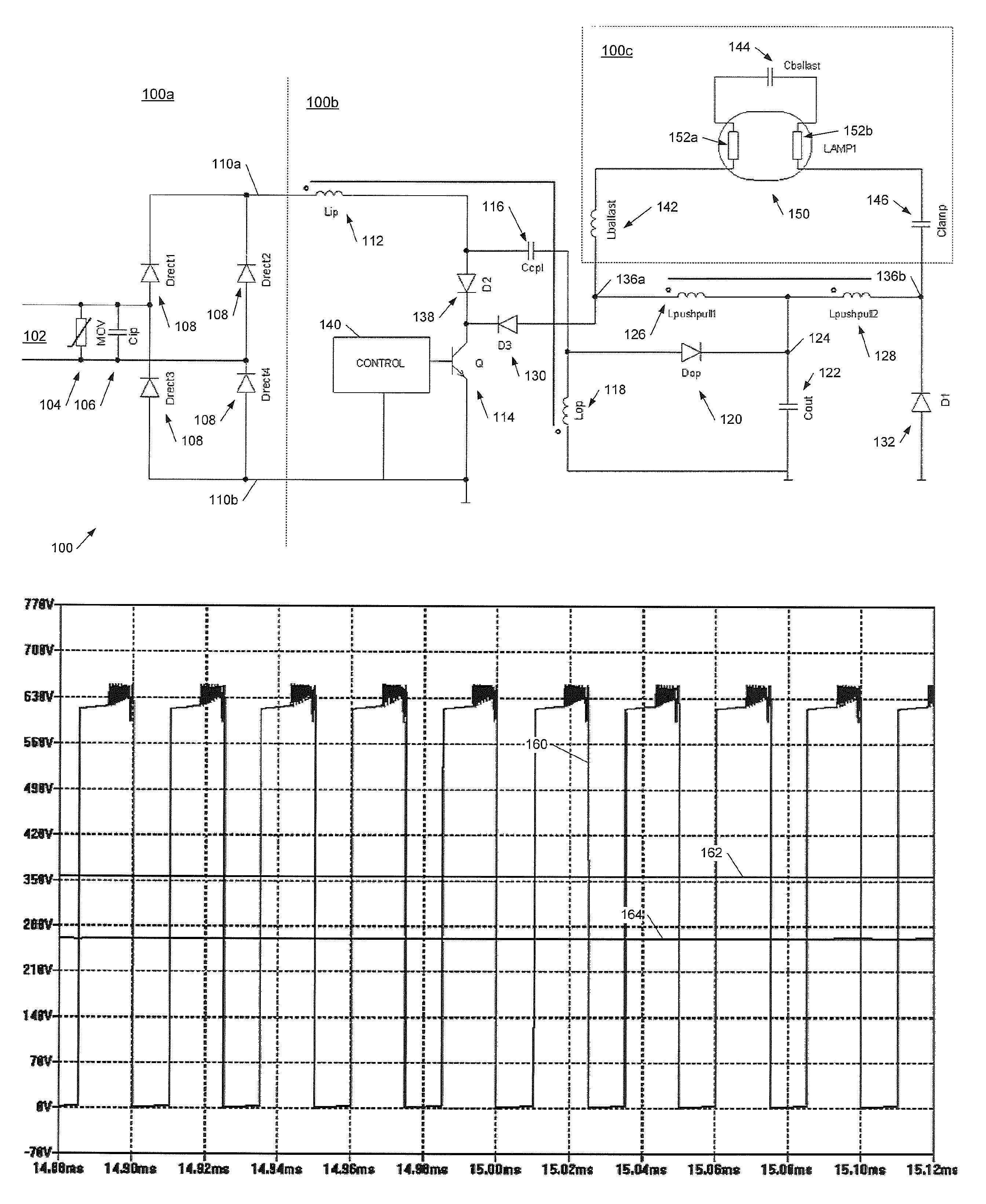
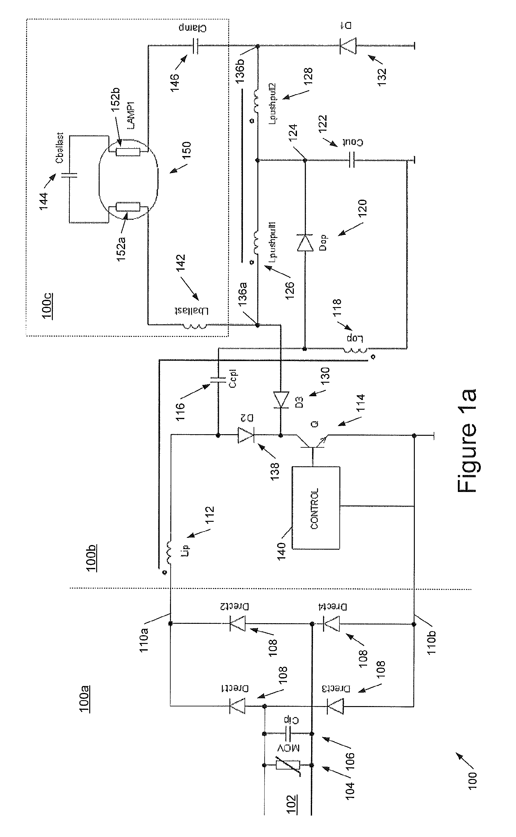
[0047]Referring now to FIG. 6, this shows an alternative design for a lighting controller (electronic ballast) 600 which employs a half bridge output stage rather than using a push-pull topology. In the arrangement of FIG. 6 like elements to those of FIG. 1a are indicated by like reference numerals, and it will be appreciated that the mains rectification stage 100a and lamp circuit 100c correspond to those shown in FIG. 1a. However the arrangement of FIG. 6 employs a SEPIC converter 600a coupled to a half bridge output stage 600b to provide an ac voltage output to the lamp circuit 100c. The half bridge output stage comprises a half bridge driver 602, which may be synchro...


PUM


Abstract

This invention generally relates to lighting controller, more particularly to electronic ballast circuits, sometimes referred to as electronic control gears (ECG) or gas discharge lamps. An electronic ballast for a gas discharge lamp, the electronic ballast comprising: a power input circuit to provide a dc voltage supply; a SEPIC converter having a converter input coupled to said dc voltage supply and having a dc voltage output; and a push-pull output stage coupled to said dc voltage output to provide an ac voltage for driving said lamp, said push-pull output stage comprising a pair of inductive elements each having a first connection to one another and to said dc voltage output and a second connection to a respective switch.

Description

FIELD OF THE INVENTION[0001]This invention generally relates to lighting controllers, more particularly to electronic ballast circuits, sometimes referred to as electronic control gears (ECG) for gas discharge lamps.BACKGROUND TO THE INVENTION[0002]The use of a SEPIC (Single-Ended Primary Inductance Converter) converter a fluorescent lamp ballast circuit is described in “SEPIC converter to perform power factor correction in a ballast for fluorescent lamps”, O. Busse, S. Mayer, B. Schemmel, A. Storm (Osram GmbH), IEEE Reference 01518852. This describes a standard circuit of a ballast for fluorescent lamps comprising a boost converter followed by a half bridge, one of the disadvantages of the boost converter being that the dc output voltage is always greater than the dc input voltage. The paper describes the use of a SEPIC converter which enables the dc output voltage driving the half bridge to be greater or less than the input voltage thus providing increased flexibility. However thi...

Claims


Application Information

Patent Timeline
Patent Type & Authority Patents(United States)
IPC IPC(8): H05B37/00
CPCH05B41/2822H05B41/2821
Inventor VAIL, DAVID
Owner POWER INTEGRATIONS INC
Why Eureka
Try Eureka