Compliant rail linear guide

a linear guide and rail technology, applied in the direction of linear bearings, rotary bearings, shafts and bearings, etc., can solve the problems of loose carriages and many adjustments, and achieve the effects of low production cost, unlimited carriage travel, and simple and lower cost design

Inactive Publication Date: 2007-10-04
FULTON STEVEN
View PDF11 Cites 3 Cited by
  • Summary
  • Abstract
  • Description
  • Claims
  • Application Information

AI Technical Summary

Benefits of technology

[0018]Because this compliant rail is able to move relative to the rail support, the guide rollers in the carriage may be fixed and do not need to be adjustable. This is a simpler and lower cost design than those with adjustable rollers. The rollers are positioned so that when the carriage is slid onto the rail assembly, the floating track moves and compresses the compliant element. This compression creates a slight preload between the carriage and the rail assembly. The compliant rail adjusts dynamically to accommodate inaccuracies of component tolerances as well as deviations in track parallelism. The carriage maintains it's preload without getting loose or binding.
[0019]The inventive design is simple, low cost to produce and addresses the needs of most applications that call for this type of product. This design can be incorporated into 3 or 4 roller carriage designs, and enables unlimited, long stroke carriage travel. The inventive design provides an easy way to set the fit-up of a linear guide carriage in the rail, and does not require any initial or ongoing adjustments.

Problems solved by technology

This is difficult and usually requires several adjustments.
If it is not done correctly, the carriage will be loose at some points and tight in others as it travels from one end of the rail to the other.

Method used


Image

  • Compliant rail linear guide
  • Compliant rail linear guide

Examples


Embodiment Construction

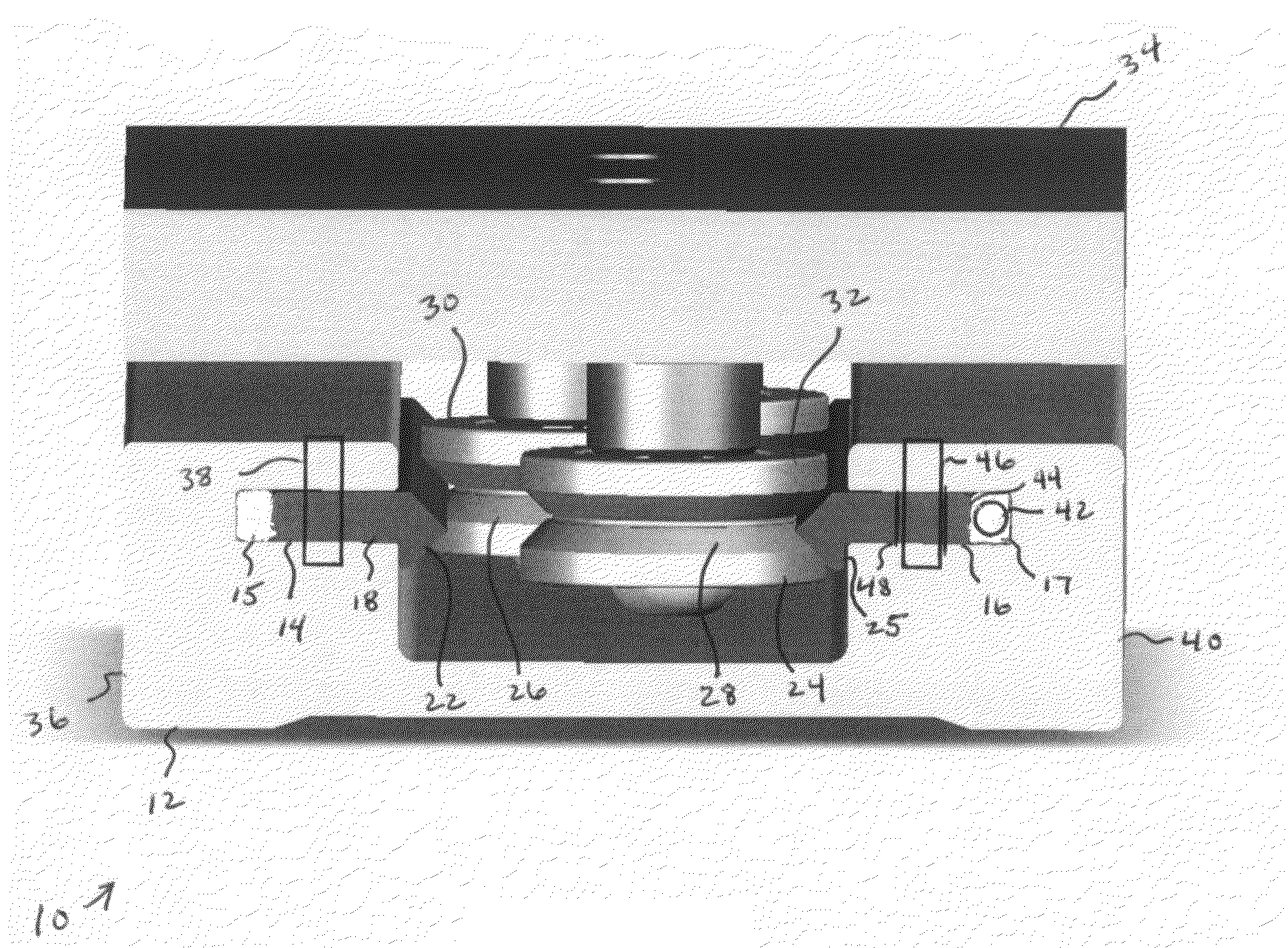
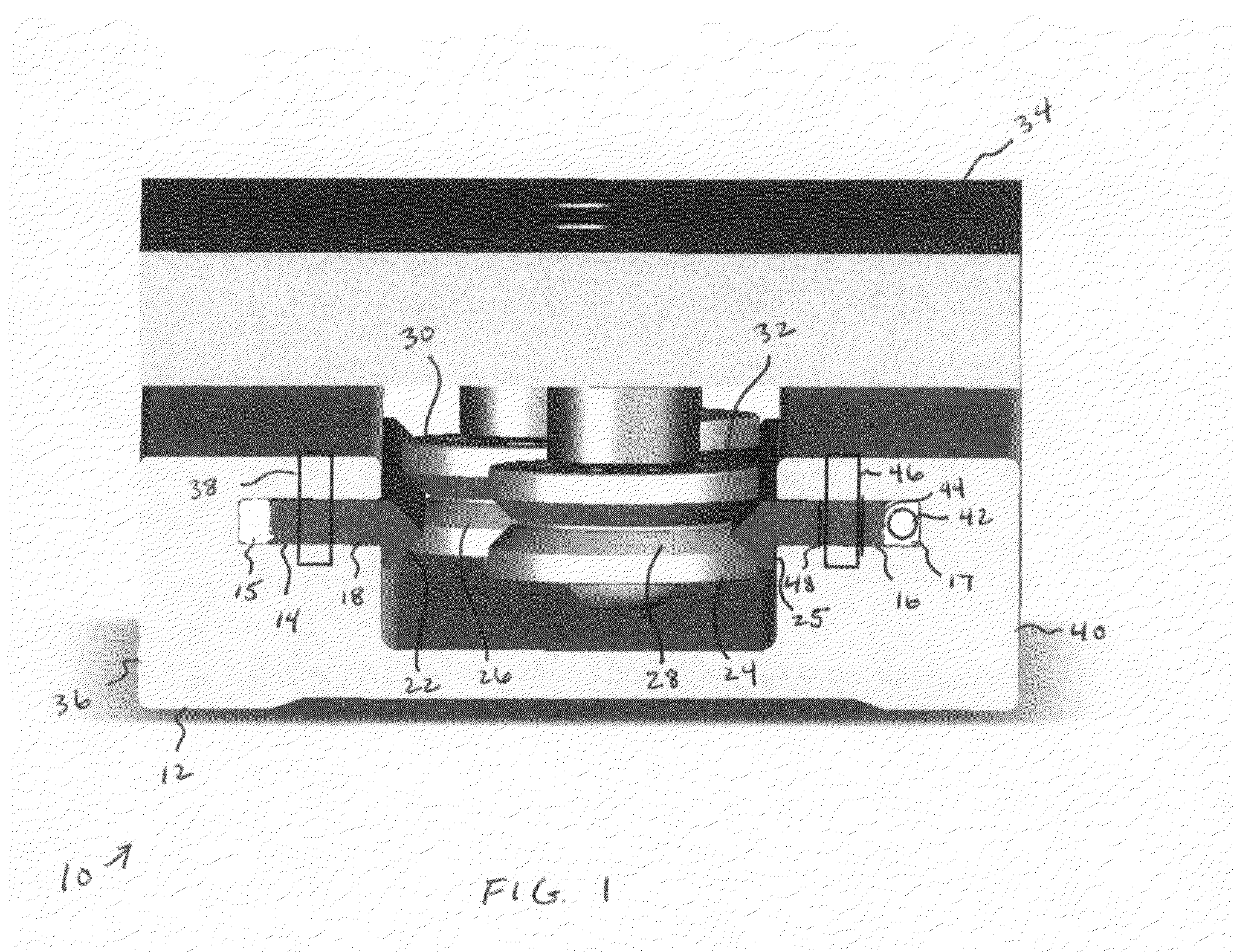
[0030]Referring to FIG. 1, there is illustrated therein a new and improved compliant rail linear guide apparatus, generally denominated 10 herein. FIG. 1 is an end view of a three roller embodiment of a compliant linear guide assembly of this invention. The inventive compliant rail assembly is equally applicable to a four roller embodiment.

[0031]The inventive apparatus 10 includes a rail support member 12 with a pair of opposing track slots 14, 16, each slot adapted to accommodate a track section 18, 20 terminating in a V-shaped proximal edge 22, 24 to mate with the groove 26, 28 in the guide rollers 30, 32 of a carriage 34. One side 36 of the rail support 12 has its track section 18 fixed into its slot 14, fastened by track mounting pin 38 to the rail support 12 at the ends to lock it into place. The opposing (compliant) side 40 of the rail support 12 holds its track section 20 in a slot 16 with a generally square recess 17 to accommodate a compliant (soft) element 42 behind the tr...


PUM


Abstract

An improved rail and track assembly for a linear guide apparatus includes a rail support member with a pair of opposing track slots, each slot adapted to accommodate a track section terminating in a V-shaped proximal edge to mate with the groove in the guide rollers of a carriage. One side of the rail support has its track section fixed into its slot, pinned to the rail support at the ends to lock it into place. The opposing side of the rail support holds its track section in a similar slot and additionally accommodates a compliant (soft) element behind the track section. The compliant element fits in a recess between the bottom of the track slot and the flat distal edge of the track section. This second track section may also be pinned to the rail support at the ends to retain it in the slot, but preferably uses oversized holes in the track to allow it to move in and out of the slot and relative to the rail support to maintain fit-up with the guide rollers of the carriage. Because this compliant rail is able to move relative to the rail support, the guide rollers in the carriage may be fixed and do not need to be adjustable.

Description

CROSS REFERENCE TO RELATED APPLICATIONS[0001]The present application claims the benefit of the filing date of U.S. Provisional Patent Application Ser. No. 60 / 786,946, filed Mar. 28, 2006.STATEMENT REGARDING FEDERALLY SPONSORED RESEARCH OR DEVELOPMENT[0002]Not applicable.REFERENCE TO A MICROFICHE APPENDIX[0003]Not applicable.TECHNICAL FIELD[0004]The present invention relates generally to linear guide apparatus, and more particularly to an improved rail and track assembly for a linear guide apparatus.BACKGROUND INFORMATION AND DISCUSSION OF RELATED ART[0005]Traditional linear guide designs use a machined rail support to accept the two opposing track sections, which are bolted down to the top of the rail support. The support is typically made from aluminum, while the track sections are made of hardened steel with a V-shape on one side. Guide rollers with mating V-grooves are mounted to an aluminum plate to make a sliding carriage. The carriage rolls between the tracks along its length....

Claims


Application Information

Patent Timeline
Patent Type & Authority Applications(United States)
IPC IPC(8): F16C19/00
CPCF16C29/045F16C29/005
Inventor FULTON, STEVEN
Owner FULTON STEVEN
Why Eureka
Try Eureka