Actuator apparatus for controlling a valve mechanism of a suspension system

a technology of suspension system and actuator, which is applied in the direction of suspension, shock absorber, operating means/releasing devices of valves, etc., can solve the problem of limiting the ability of the rider to customize the damping characteristics of the suspension system

Active Publication Date: 2006-12-12
SRAM CORPORATION
View PDF9 Cites 80 Cited by
  • Summary
  • Abstract
  • Description
  • Claims
  • Application Information

AI Technical Summary

Benefits of technology

[0005]The objective of the present invention is to provide an actuator apparatus for adjusting the damping of a suspension system that allows the rider to customize the damping characteristics of the system to suit the terrain or the rider's particular riding style. The present invention provides an actuator apparatus for controlling a valve mechanism for a suspension system. The actuator apparatus generally includes a valve actuating assembly and an adjuster assembly. The valve actuating assembly adjusts the valve mechanism between various suspension settings. The adjuster assembly is operatively connected to the valve actuating assembly for adjusting the damping characteristics corresponding to at least one of the positions of the valve actuating assembly independently of the damping characteristics corresponding to another position of the valve actuating assembly.
[0008]In another embodiment of the present invention, a lever is rigidly attached to the camshaft having three cam surfaces. However, in this embodiment all three of the cam surfaces are substantially parallel to the camshaft axis and a setscrew engages the camshaft to prevent axial movement of the camshaft while still allowing rotational movement of the camshaft. A detent mechanism positions the lever such that when one of the three rider-selectable positions is selected, the corresponding cam surface is perpendicular to the driver. This embodiment further includes a stop element that prevents over-rotation of the lever. The adjuster assembly includes a limit screw. The limit screw is configured such that when it is fully retracted all three of the cam surfaces are perpendicular to the driver. However, when the limit screw is partially or fully advanced, the stop element contacts the end of the limit screw and prevents the lever and the camshaft from fully rotating to the third position. In this position, the cam surface corresponding to the third position is prevented from rotating perpendicular to the driver and is held at an angle relative to the driver. Accordingly, the amount in which the limit screw is advanced or retracted determines the damping characteristics of the third position of lever.

Problems solved by technology

One problem associated with this configuration is that any given angular position of the lever / cam corresponds to exactly one position of the adjuster rod.
This limits the ability of the rider to customize the damping characteristics of the suspension system to suit the terrain or the rider's particular riding style.

Method used


Image

  • Actuator apparatus for controlling a valve mechanism of a suspension system
  • Actuator apparatus for controlling a valve mechanism of a suspension system
  • Actuator apparatus for controlling a valve mechanism of a suspension system

Examples


Embodiment Construction

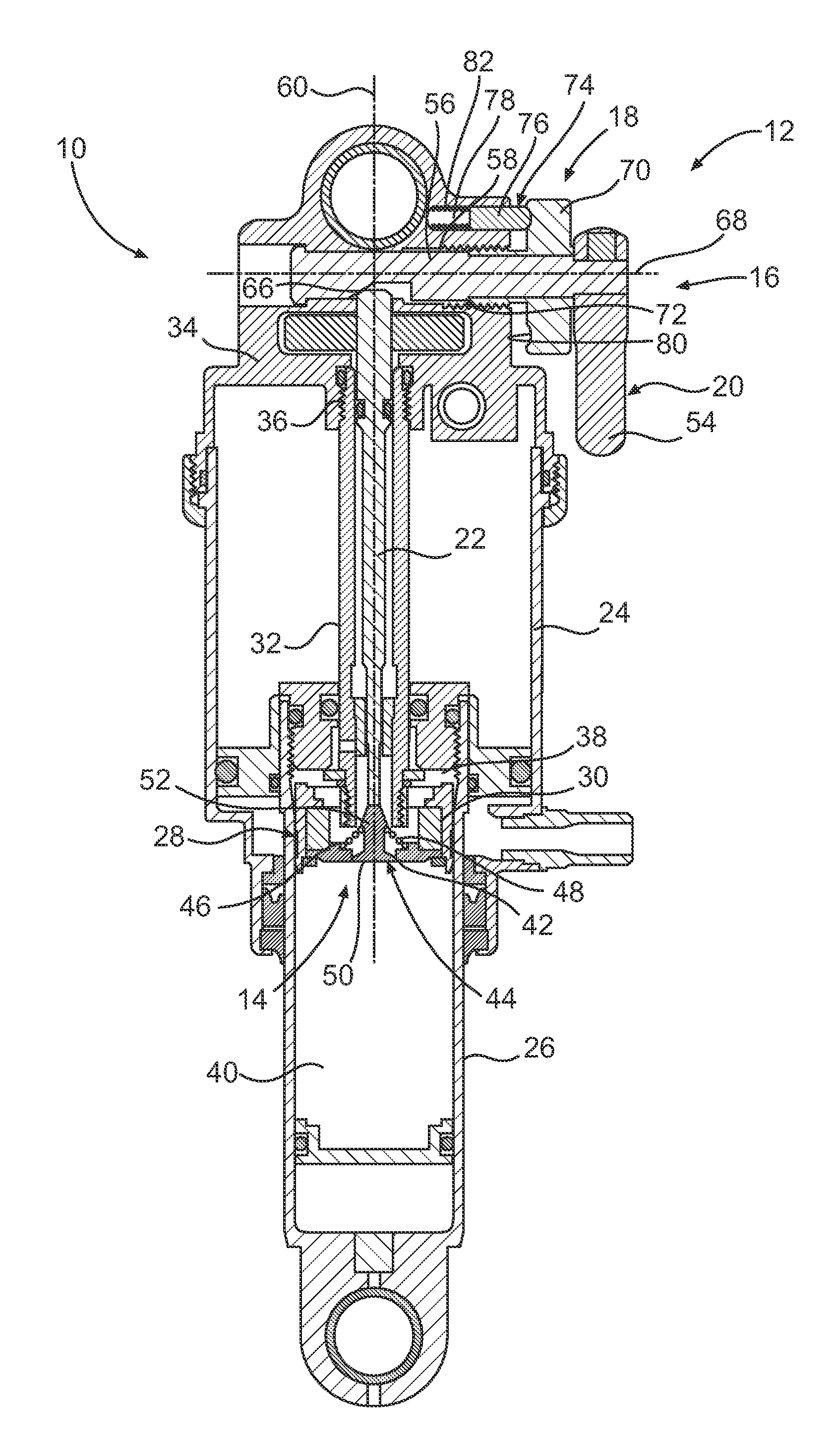
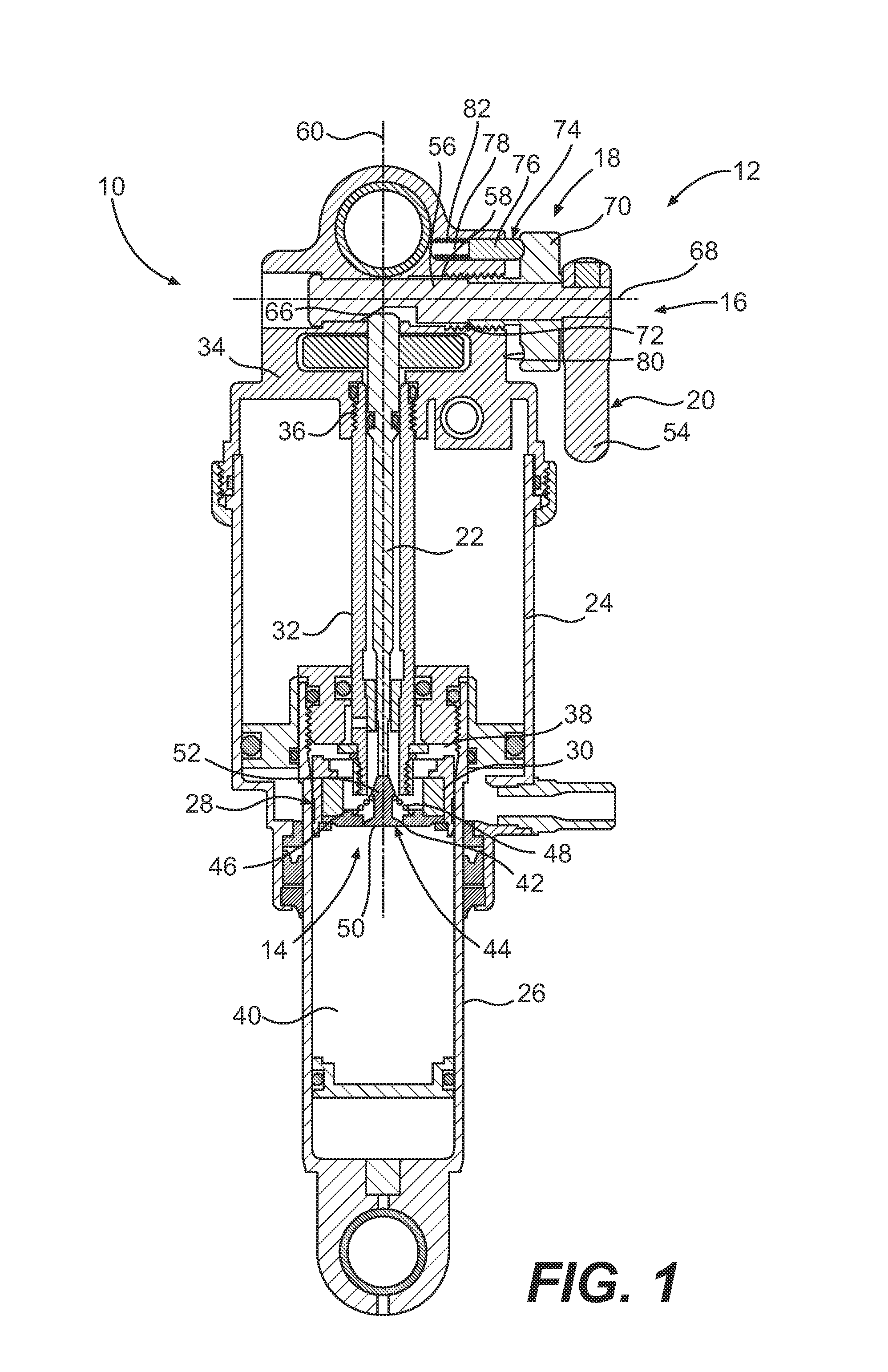
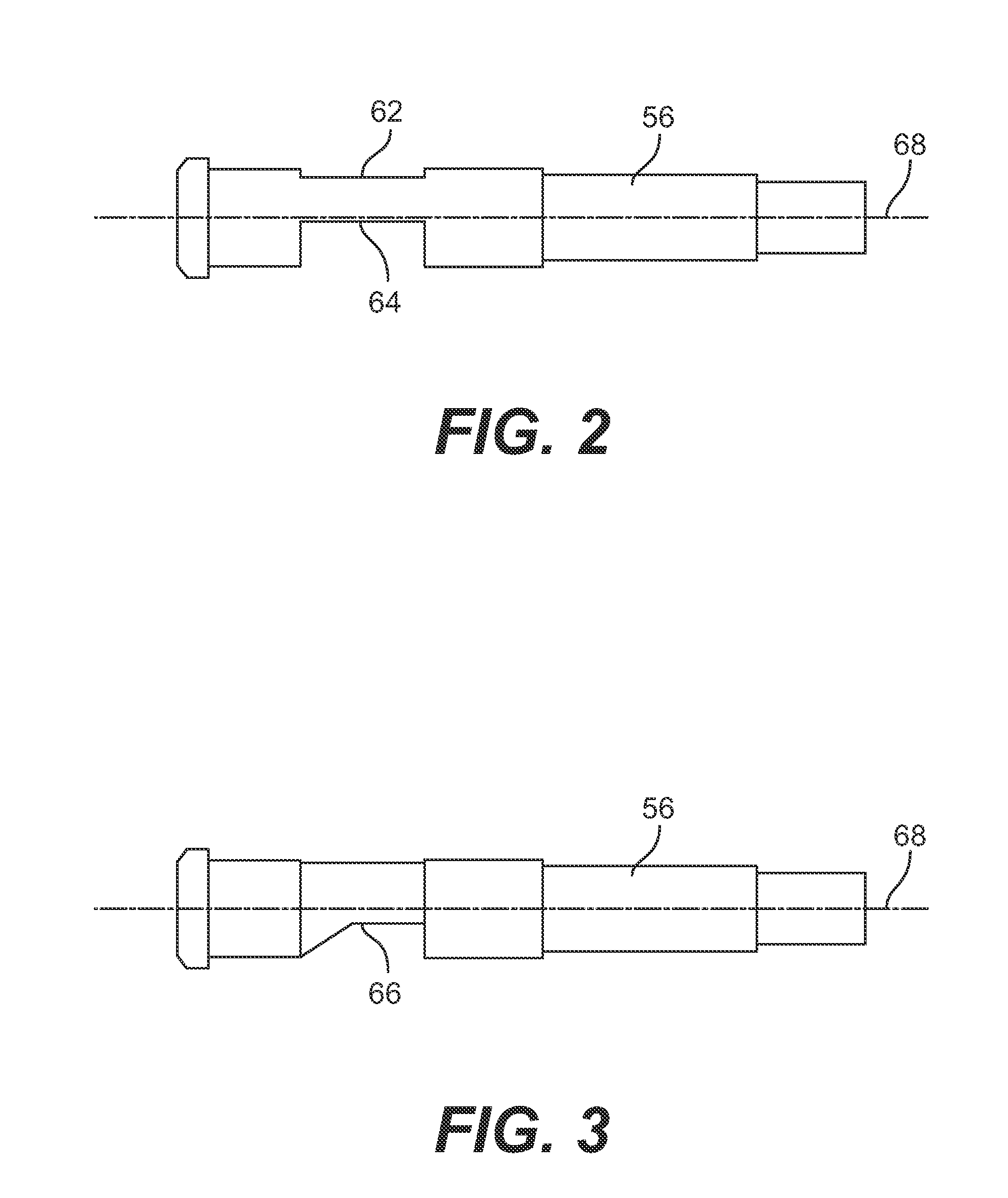
[0021]FIGS. 1–6 illustrate a suspension system 10 having an actuator apparatus 12 for controlling a valve mechanism 14 in accordance with one embodiment of the present invention. The actuator apparatus 12 generally includes a valve actuating assembly 16 operable between at least two rider-selectable positions to adjust the valve mechanism 14 between various suspension settings and an adjuster assembly 18 operatively connected to the valve actuating assembly 16 to adjust the damping characteristics corresponding to at least one of the positions of the valve actuating assembly 16 independently of the damping characteristics corresponding to another position of the valve actuating assembly 16. The valve actuating assembly 16 includes a selector 20 having at least two rider-selectable positions and a driver 22 movable to adjust the valve mechanism 14 between various suspension settings. In this embodiment, the selector 20 has three rider-selectable positions representing open, lockout a...


PUM


Abstract

An actuator apparatus controls a valve mechanism of a suspension system. The apparatus includes a valve actuating assembly and an adjuster assembly. The valve actuating assembly is operatively connected to the valve mechanism and is operable between at least two rider-selectable positions to adjust the valve mechanism between various suspension settings. The adjuster assembly is operatively connected to the valve actuating assembly for adjusting the damping characteristics corresponding to at least one of the positions of the valve actuating assembly independently of the damping characteristics corresponding to another position of the valve actuating assembly.

Description

BACKGROUND OF THE INVENTION[0001]The present invention relates to suspension systems and more particularly to an actuator apparatus for controlling a valve mechanism of a suspension system that includes a valve actuating assembly operable between at least two rider-selectable positions and an adjuster assembly for adjusting the damping characteristics of at least one of the rider-selectable positions.[0002]Typically, a suspension system includes a piston disposed in a cylinder of housing for reciprocation therein. The piston divides the cylinder into two opposed chambers. A piston shaft is connected to the piston and extends from the piston to a position outside of the cylinder. A fluid, such as oil, or air, or the like, is normally contained in the chambers. In use, the fluid passes between the chambers in response to reciprocation of the piston in the cylinder to affect damping.[0003]The damping characteristics of a suspension system can affect the quality of performance provided ...

Claims


Application Information

Patent Timeline
Patent Type & Authority Patents(United States)
IPC IPC(8): F16K31/44
CPCB60G17/08F16F9/461
Inventor JORDAN, BRIANWESLING, KEVINSHIPMAN, CHRISTOPHERSWAIDNER, ERICCHEEVER, JOHN
Owner SRAM CORPORATION
Why Eureka
Try Eureka