Thickness control method and double side polisher

a technology of thickness control and polisher, which is applied in the direction of grinding machine components, manufacturing tools, lapping machines, etc., can solve the problems of affecting the thickness of the polishing plate no longer corresponds to the amount of material, and the end of the stylus is abraded, so as to achieve high accuracy and maintain the thickness control performance

Inactive Publication Date: 2006-12-12
SPEEDFAM CO LTD
View PDF18 Cites 54 Cited by
  • Summary
  • Abstract
  • Description
  • Claims
  • Application Information

AI Technical Summary

Benefits of technology

[0010]In contrast, in the thickness control device using the eddy current sensor disclosed in the second Document, the distance between the upper and lower polishing plates is detected by radiating magnetic field from the eddy current sensor to the lower polishing plate, which allows for measurements including the wear of the lower polishing plate, and also allows the measurement of the work piece to an accuracy of ±3 μm or less, since measurement error decreases compared with the thickness control device disclosed in the first document.
[0015]An object of the present invention is to provide a double side polisher capable of maintaining accuracy of thickness control over a long period of time without being affected effectively by the thickness change of a polishing plate, and a thickness control method for a double side polisher.
[0022]According to the double side polisher and the thickness control method of the present invention, calibration of the drift in measured value caused by the change in thickness of the polishing pad due to various factors such as abrasion, compression, swelling, etc. is performed after each polishing operation, and therefore it is possible to maintain a thickness control performance with high accuracy over a long period of time. In addition, since the distance to the surface of the carrier is measured, it is possible to apply the present invention to such nonconductive work pieces as semiconductor wafers without depending on their electrical property.

Problems solved by technology

However, as the upper and lower polishing plates are worn while lapping operations are repeated, the displacement of the upper polishing plate becomes no longer correspond to the amount of material removal when many work pieces are polished.
Moreover, since the stylus is in contact with the chip, the contact end of the stylus is abraded by rotation of the chip and error in measurement may occur.
Because of this, accuracy the thickness control is about ±4 to 5 μm and thus it is difficult to achieve an accuracy of ±3 μm or less.
However, accuracy achieved by the above thickness control device is not enough to satisfy the level recently required as the measurement is influenced by deformation of polishing pad caused by polishing pressure.

Method used


Image

  • Thickness control method and double side polisher
  • Thickness control method and double side polisher
  • Thickness control method and double side polisher

Examples


Embodiment Construction

[0029]Now, preferred embodiments of the present invention will be described in detail while referring to the accompanying drawings.

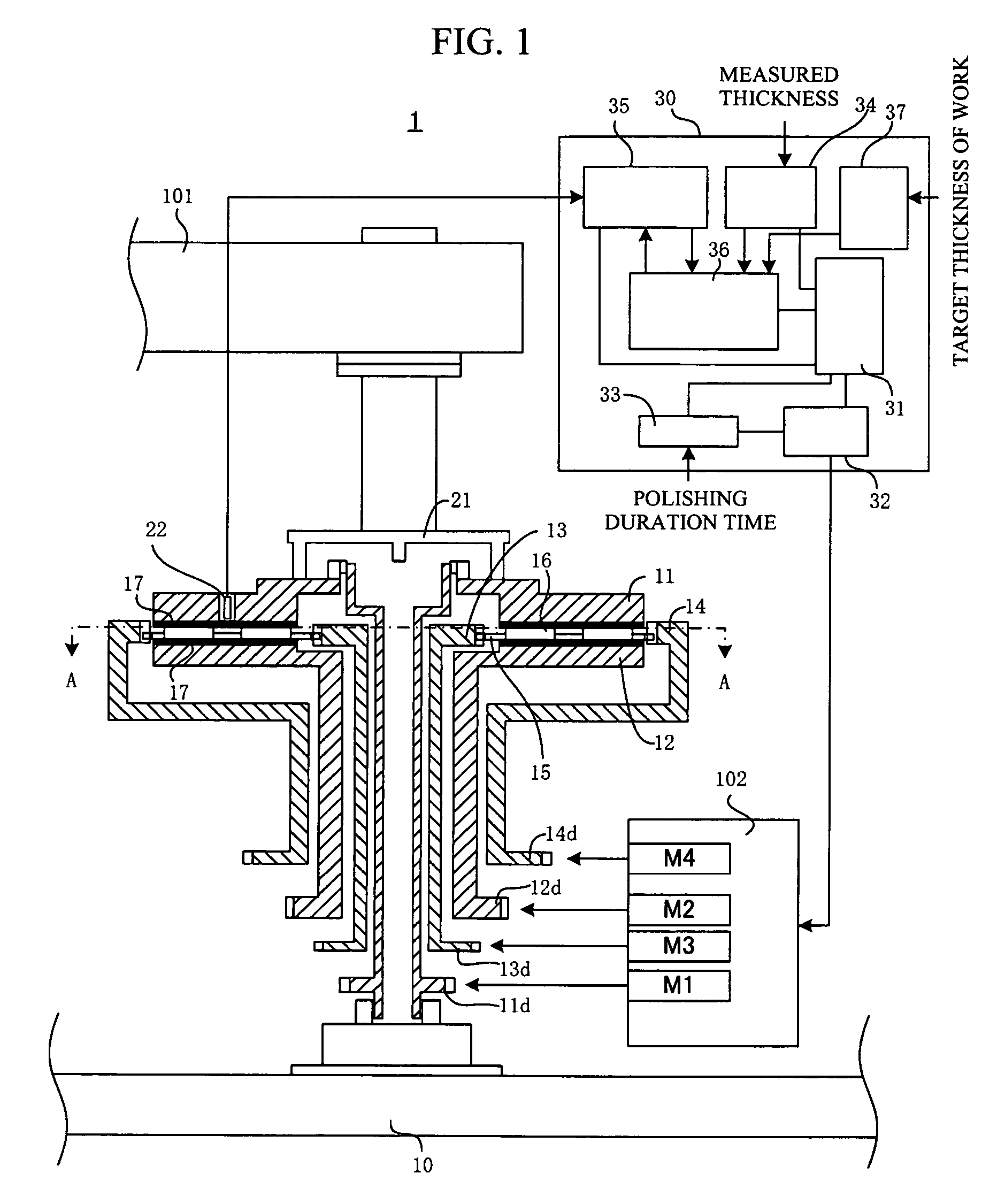
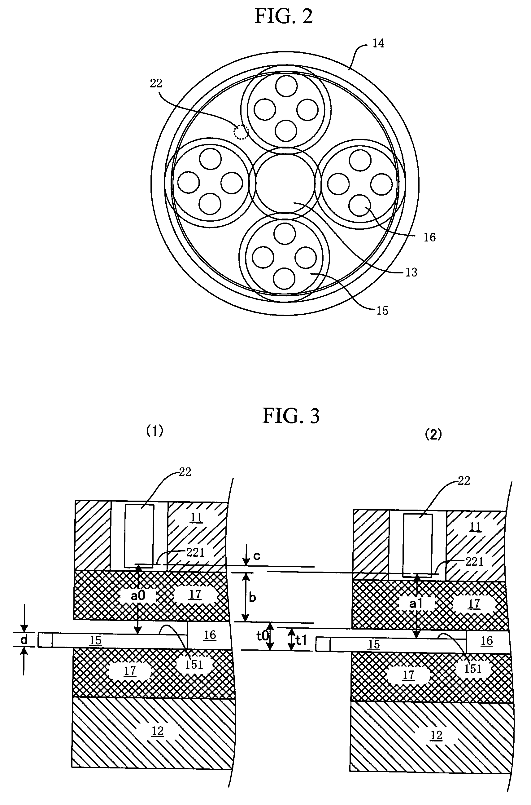
[0030]FIG. 1 shows a substantial part of an example of double side polisher according to the present invention. FIG. 2 is a plan view as seen from A—A of FIG. 1.

[0031]An upper polishing plate 11, a lower polishing plate 12, a sun gear, and an internal gear 14 are supported rotatably around the same axis on a machine base 10. The upper polishing plate 11 , the lower polishing plate 12, sun gear 13, and internal gear 14 have integrally a first drive gear 11d, a second drive gear 12d, a third drive gear 13d, and a fourth drive gear 14d respectively in order to transmit rotation power. To these gears, rotation power from a first motor M1, a second motor M2, a third motor M3, and a fourth motor M4 are transmitted respectively. Although a drive unit 102 shown here consists of four motors, it is possible to drive respective gears with a single motor by distribu...


PUM

PropertyMeasurementUnit
thicknessaaaaaaaaaa
thicknessaaaaaaaaaa
thicknessaaaaaaaaaa

Abstract

The object of the present invention is to provide a double side polisher capable of maintaining thickness control accuracy over a long period of time without being affected by a gradual change in thickness of a polishing pad, and a thickness control method. The first polishing operation is finished based on the polishing duration time, and the second and subsequent polishing operations are finished based on the measured distance values of a distance sensor, and after each polishing operation including the first polishing, the measured value of the distance sensor is calibrated based on the measured value and target value of finishing thickness of the work piece. Since the calibration is performed for each polishing operation, it is possible to maintain thickness control accuracy over a long period of time.

Description

[0001]This application is based on application No. 2005-050404 filed in Japan, the contents of which are hereby incorporated by reference.FIELD OF THE INVENTION[0002]The present invention relates to a double side polisher for a work piece and a thickness control method thereof.BACKGROUND OF THE INVENTION[0003]A double side polisher is a machine that polishes surfaces of both sides of a work piece at the same time. The work pieces are inserted in holes of a carrier respectively and the carrier with the work pieces is placed between upper and lower polishing plates on which polishing pads are plastered. Then, a planetary motion is provided to the carrier and a rotary motion is provided to the upper and lower polishing plates, while supplying slurry in the gap of the polishing plates and applying a predetermined polishing pressure to the work pieces by the polishing plates.[0004]Although the amount of polishing of the work piece is usually monitored by means of polishing duration time,...

Claims


Application Information

Patent Timeline
Patent Type & Authority Patents(United States)
IPC IPC(8): B24B49/00B24B37/07B24B37/08B24B49/05
CPCB24B37/08B24B41/067B24B49/02B24B49/10
Inventor NAGAYAMA, HITOSHIINOUE, YUSUKE
Owner SPEEDFAM CO LTD
Why Eureka
Try Eureka