
Supplemental restraint for auto-rack railroad car restraint system

a technology for auto-rack cars and restraint systems, which is applied in braking systems, transportation and packaging, transportation items, etc., can solve problems such as the potential damage of newly-manufactured vehicles in auto-rack cars, the development of restraint systems in relation to new types of vehicles, and the effect of reducing the risk of collision

Inactive Publication Date: 2006-12-19
GE GLOBAL SOURCING LLC
View PDF59 Cites 33 Cited by
  • Summary
  • Abstract
  • Description
  • Claims
  • Application Information

AI Technical Summary

Benefits of technology

[0026]It is, therefore, an advantage of the present invention to provide a supplemental restraint for a restraint system for a vehicle transported in an auto-rack railroad car.

Problems solved by technology

One problem with auto-rack cars is the potential for damage to newly-manufactured vehicles which can occur in the auto-rack car due to the unwanted movement of one or more of the transported vehicles not adequately secured in the auto-rack car.
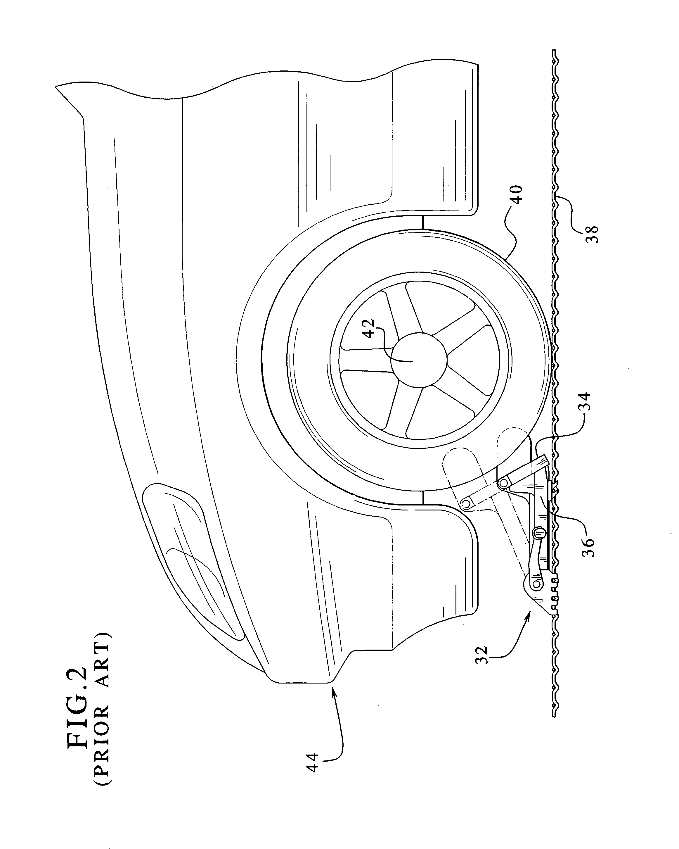
While the primary restraint system described above (and described in more detail in U.S. Pat. Nos. 5,239,933 and 5,302,063) has been widely adapted and generally relatively effective in restraining vehicles, such as conventional automobiles, vans, trucks and certain SUVs, a problem has developed in relation to new types of vehicles, currently called “cross-over” vehicles.
When cross-over vehicles are loaded in an auto-rack railroad car on the grating of the vehicle restraint system described above, it has been found that the restraint system and, particularly, the primary restraints are not adequately holding these vehicles in place or preventing the movement of the vehicles to a minimum desired level of movement.
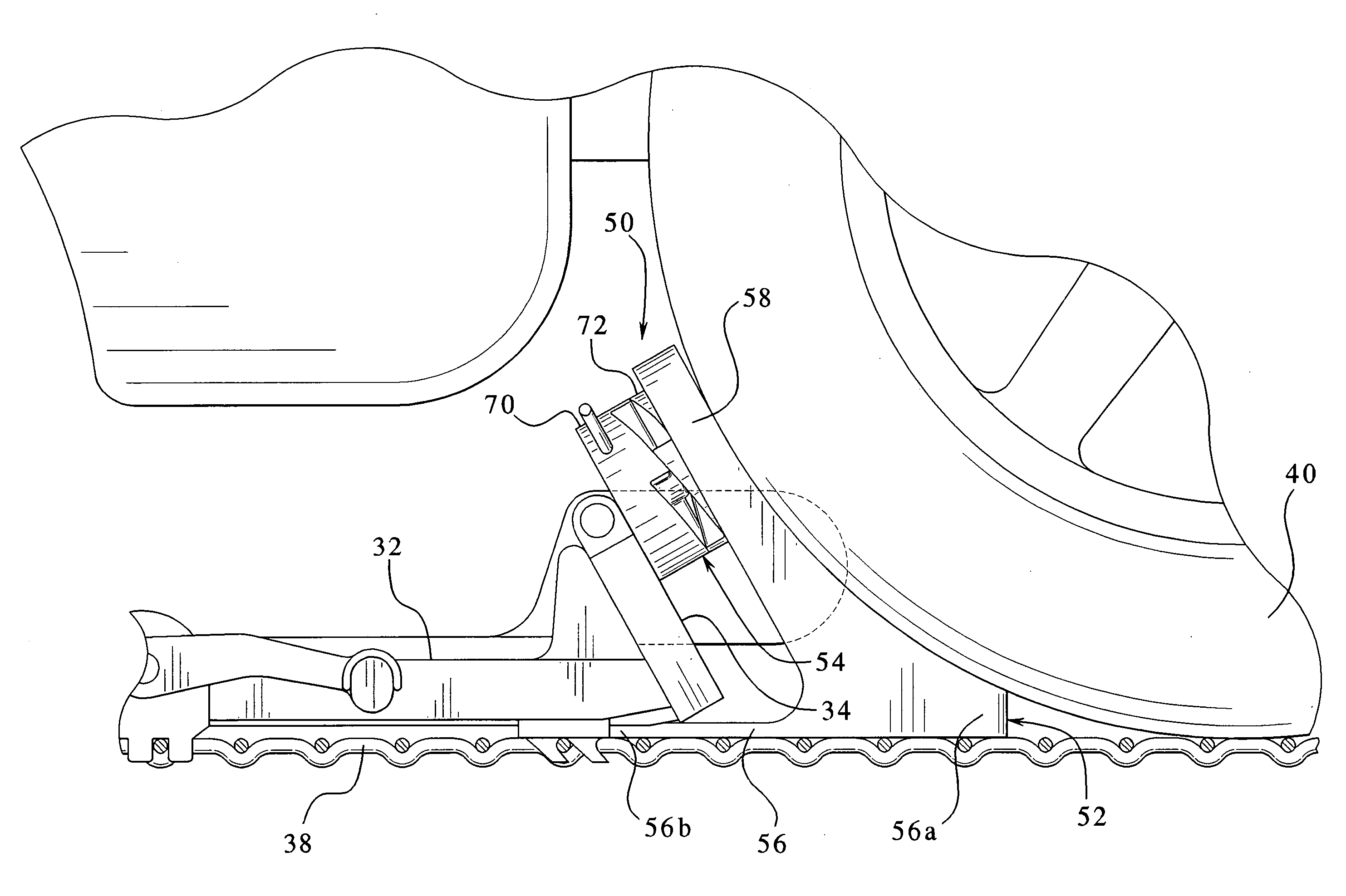
A related problem which can also cause the vehicle to be more likely to jump over or hop the primary restraint is that the primary restraint is sometimes not placed as close to the tire as potentially possible as also illustrated in FIG. 2.
A similar problem arises because the primary restraint may need to be positioned or spaced at a distance from the tire because the tire is at a position on the grating or relative to the grating that does not allow the primary restraint to be placed in engagement with the tire.
This gap problem is compounded because certain vehicle manufacturers require that certain vehicles be transported with the transmission in neutral to prevent damage to the vehicle such as to the transmission of the vehicle.
The amount of force on the vehicles being transported relative to the auto-rack car can cause the vehicles to hop or jump over the primary restraints, especially if the tire is engaged by the face-plate at a relatively low point, if the primary restraint is spaced from the tire or if the face-plate is at a low position and spaced from the tire.
These jolts can cause extreme force on the vehicles relative to the railroad cars and, thus, cause the vehicles to jump or hop the primary restraints especially if the tire is engaged by the face-plate at a relatively low point or if the primary restraint is spaced from the tire.
There have been significant recorded instances of this type of damage to vehicles and especially cross-over vehicles in auto-rack railroad cars in railroad yards in recent years.
As indicated above, such damage to the vehicles necessitates the replacement of the damaged part and potentially other parts of the vehicle.
This damage is extremely expensive for vehicle manufacturers which charge the railroads for such damage.
This problem is compounded for vehicle manufacturers when the vehicle damaged is a specially ordered vehicle (instead of a stock vehicle) for a specific customer.
If the specially ordered vehicle is damaged in transit, the customer may need to wait for another specially ordered vehicle to be manufactured.
This can harm the dealer's and manufacturer's businesses.
Additionally, the railroads often incur significant expenses because the end doors of the auto-rack railroad cars need to be repaired.
The primary restraints are also often damaged when the vehicles jump the primary restraints or run into the primary restraints.
This causes additional expenses which are incurred by the railroads.
It should thus be recognized that while the restraint system described above, which has been widely commercially implemented, provides certain restraint for vehicles being transported in auto-rack cars, in certain instances this restraint system does not adequately protect the vehicles or prevent the movement of the vehicles and thus prevent damage to the vehicles, the auto-rack railroad cars and the primary restraints.

Method used


Image

  • Supplemental restraint for auto-rack railroad car restraint system
  • Supplemental restraint for auto-rack railroad car restraint system
  • Supplemental restraint for auto-rack railroad car restraint system

Examples


Embodiment Construction

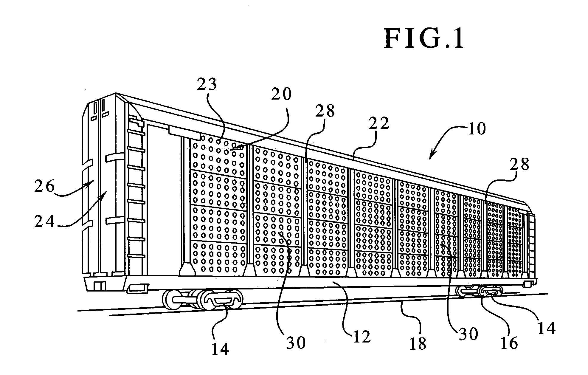
[0054]Referring now to the drawings, and, particularly, to FIG. 1, a typical auto-rack railroad car 10 includes a frame 12 supported by trucks 14, each of which have several wheels 16 which roll along railroad tracks 18. The frame 12 supports two sidewalls 20 and a roof 22. The auto-rack car 10 includes a pair of co-acting clamshell doors 24 and 26 mounted on each end of the auto-rack car 10. The doors 24 and 26 are opened to facilitate the loading and unloading of vehicles into and out of the auto-rack car 10 and are closed during transport or storage of the vehicles.

[0055]The sidewalls 20 include a series of steel vertical posts 28 which are mounted on, and extend upwardly from, the frame 12. The roof 22 is mounted on, and supported by, these vertical posts. The vertical posts are evenly spaced along the entire length of both sidewalls 20 of the auto-rack car 10. A plurality of rectangular galvanized steel sidewall panels 30 which extend horizontally and are vertically spaced apar...


PUM


Abstract

A supplemental restraint for a primary vehicle restraint system for an auto-rack railroad car which reduces or eliminates movement of the vehicle in the auto-rack railroad car. The supplemental restraint is adapted to be positioned on a grating between the tire of the vehicle and the primary restraint. One embodiment of the supplemental restraint includes a body and an expander connected to the body. After the primary restraint is locked in place on the grating, the expander of the supplemental restraint is expanded. The expansion causes a more secure engagement between the tire and the primary restraint. This causes a high level of engagement between the tire and the primary restraint system indirectly through the supplemental restraint. The supplemental restraint also maintains a higher contact area on the tire regardless of the position of the primary restraint.

Description

PRIORITY CLAIM[0001]This application is a continuation-in-part of, claims priority to and the benefit of U.S. patent application Ser. No. 10 / 644,294 now U.S. Pat. No. 6,926,480, filed on Aug. 20, 2003, the entire contents of which is incorporated herein.DESCRIPTION[0002]The present invention relates in general to a supplemental restraint for an auto-rack railroad car, and more particularly to an improved supplemental restraint for a vehicle restraint system in an auto-rack railroad car which includes a grating mounted in an auto-rack railroad car and a primary restraint removably attachable to the grating to prevent the vehicle on the grating from moving.BACKGROUND OF THE INVENTION[0003]The railroad industry employs a variety of railroad cars for transporting products including vehicles such as automobiles and trucks. Auto-rack railroad cars transport newly-manufactured vehicles such as automobiles, vans, and trucks. Auto-rack railroad cars, known in the railroad industry as auto-ra...

Claims


Application Information

Patent Timeline
Patent Type & Authority Patents(United States)
IPC IPC(8): B60T3/00B60P3/077
CPCB60P3/077
Inventor ANDERSON, JOHN D.PEACH, WALTER J.BURKE, MICHAEL K.
Owner GE GLOBAL SOURCING LLC
Learn More