Aspects of basic OCT engine technologies for high speed optical coherence tomography and light source and other improvements in optical coherence tomography

a technology of optical coherence tomography and light source, applied in the field of real-time imaging system and method, can solve problems such as interference between the intensity of respective points and the time delay of equal tim

Inactive Publication Date: 2006-06-13
UNIVERSITY HOSPITALS OF CLEVELAND CLEVELAND +1
View PDF19 Cites 231 Cited by
  • Summary
  • Abstract
  • Description
  • Claims
  • Application Information

AI Technical Summary

Benefits of technology

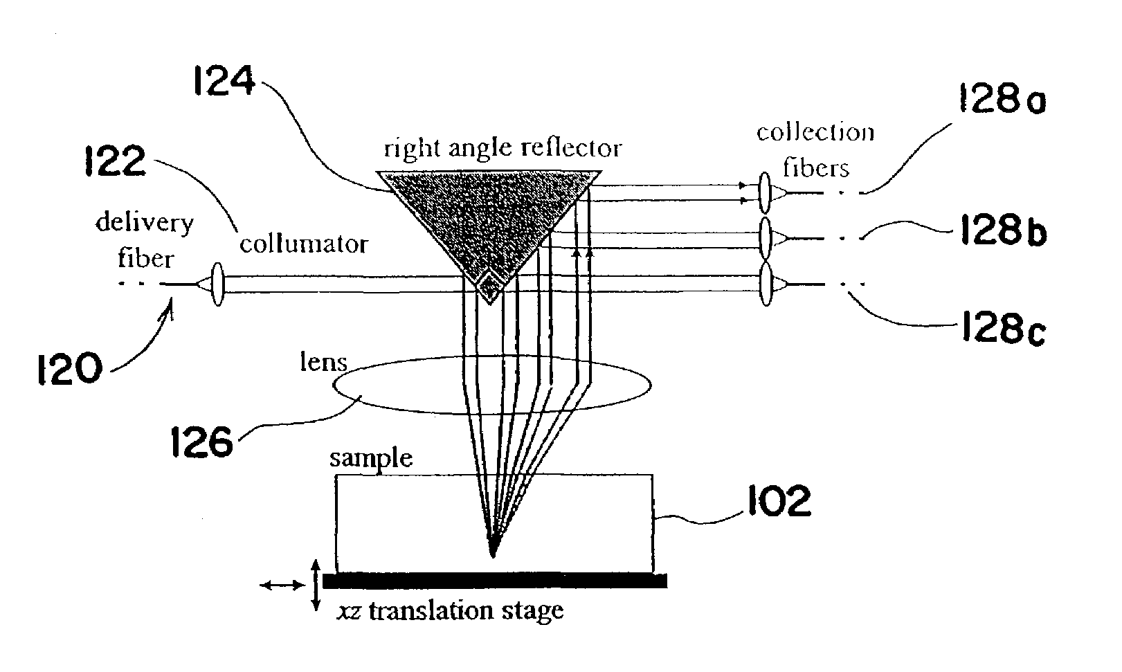
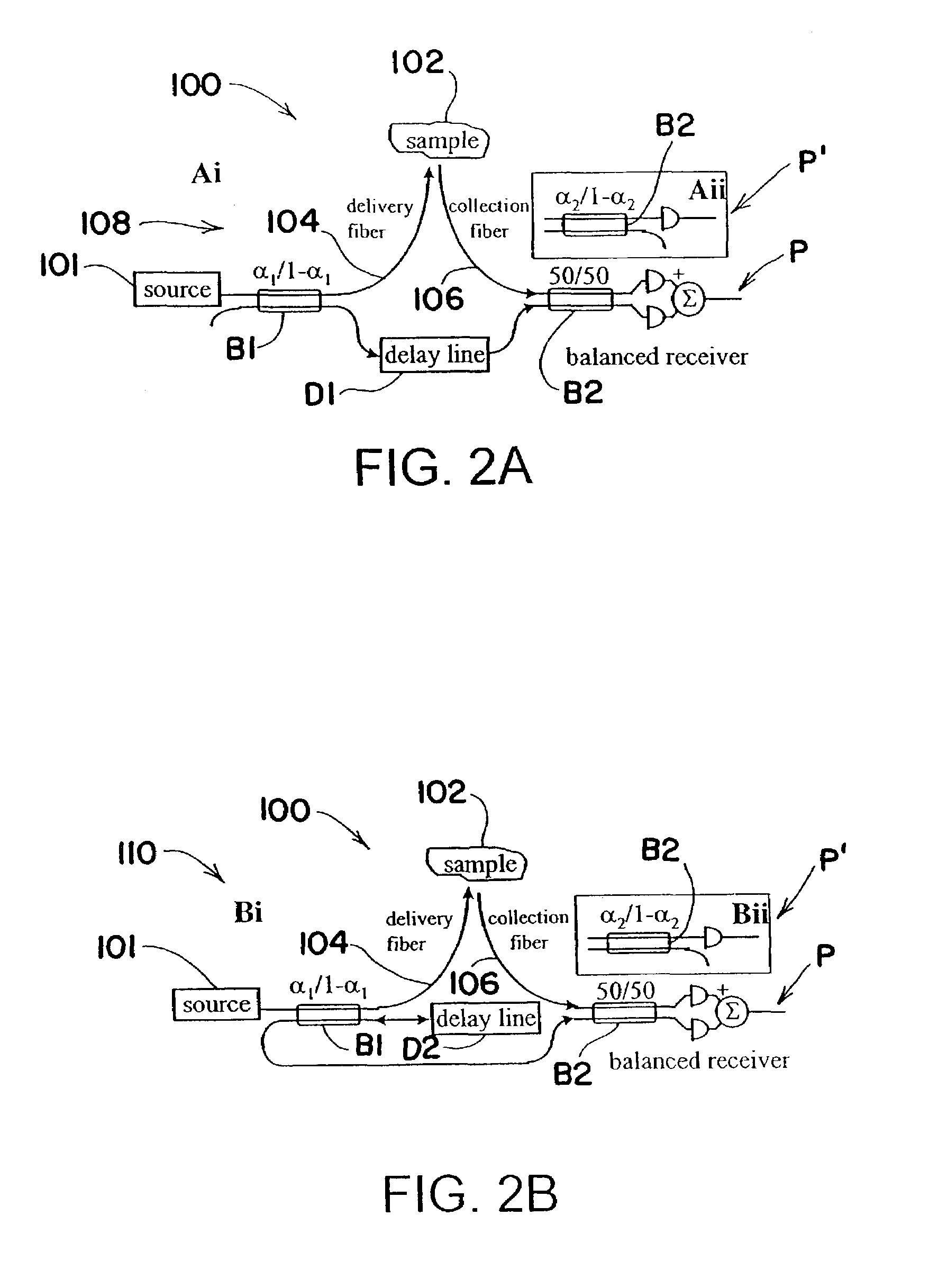
[0043]In accordance with yet another aspect of the present invention, an interferometer includes a low coherence source and a beamsplitter for directing light from the source to a sample and to a reference optical delay line. A scanning system scans a sample with the incident light from the source and a detector system detects light scattered by the sample at multiple angles.

Problems solved by technology

When the reflected beams meet, intensities from respective points with equal time delay form interference.

Method used


Image

  • Aspects of basic OCT engine technologies for high speed optical coherence tomography and light source and other improvements in optical coherence tomography
  • Aspects of basic OCT engine technologies for high speed optical coherence tomography and light source and other improvements in optical coherence tomography
  • Aspects of basic OCT engine technologies for high speed optical coherence tomography and light source and other improvements in optical coherence tomography

Examples


Embodiment Construction

1 Spectroscopic OCT

[0047]Spectroscopic OCT can be defined as a family of techniques using OCT to measure optical properties of a sample system as a function of wavelength. Methods to perform absorption spectroscopy and elastic scattering spectroscopy with depth resolution using OCT have been proposed and, to some extent, demonstrated (See M. D. Kulkarni and J. A. Izatt, “Spectroscopic Optical Coherence Tomography,” presented at Conference on Lasers and Electro-Optics, 1996, and U. Morgner, “Spectroscopic Optical Coherence Tomography,” presented at Conference on Lasers and Electro-Optics Technical Digest, Baltimore, Md., 1999, which are incorporated by reference).

[0048]This field of OCT research has not been extensively explored and represents one of the most fruitful avenues of investigation in OCT.

1.1 Wavelength Ratiometric OCT

[0049]The technique of wavelength-ratiometric OCT (WROCT) is a relatively simple spectroscopic OCT method that holds the potential to produce images using an...


PUM

PropertyMeasurementUnit
wavelengthsaaaaaaaaaa

Abstract

An optical coherence tomography (OCT) system including an interferometer provides illuminating light along a first optical path to a sample and an optical delay line and collects light from the sample along a second optical path remitted at several scattering angles to a detector. In one embodiment, illuminating light is directed along a number of incident light paths through a focusing lens to a sample. The light paths and focusing lens are related to the sample and to both the incident light source and the detector. In another embodiment, a focusing system directs light to a location in the sample. A transmission grating or acousto-optic modulator directs light from the sample at an angle representative of the wavelength of the incident light on the transmission grating or acousto-optic modulator.

Description

[0001]Applicants claim the benefit of U.S. Provisional Applications No. 60 / 310,080 and 60 / 310,083, both filed Aug. 3, 2001, the entire disclosures of which are hereby incorporated herein.FIELD OF THE INVENTION[0002]The present invention is directed to a real-time imaging system and method that is particularly useful in the medical field, and more particularly, to a system and method for imaging and analysis of tissue and other samples using optical coherence tomography.BACKGROUND OF THE INVENTION[0003]A variety of imaging techniques are used for the medical diagnosis and treatment of patients. Ultrasound imaging represents a prevalent technique. Ultrasound uses sound waves to obtain a cross-sectional image of an object. These waves are radiated by a transducer, directed into the tissues of a patient, and reflected from the tissues. The transducer also operates as a receiver to receive the reflected waves and electronically process them for ultimate display.[0004]Another imaging tech...

Claims


Application Information

Patent Timeline
Patent Type & Authority Patents(United States)
IPC IPC(8): G01B9/02G01B11/24G01N21/47
CPCG01N21/4795G01B11/2441A61B5/0066
Inventor ROLLINS, ANDREW M.IZATT, JOSEPH A.WESTPHAL, VOLKERYAZDANFAR, SIAVASH
Owner UNIVERSITY HOSPITALS OF CLEVELAND CLEVELAND
Why Eureka
Try Eureka