Far-field display

a technology of projection display and display screen, applied in the direction of static indicating device, lighting and heating apparatus, instruments, etc., can solve problems such as application to far-field imaging

Inactive Publication Date: 2005-01-25
MICROSOFT TECH LICENSING LLC
View PDF19 Cites 261 Cited by
  • Summary
  • Abstract
  • Description
  • Claims
  • Application Information

AI Technical Summary

Problems solved by technology

Two-stage optical expansion systems are known—see for instance U.S. Pat. No. 5,668,913 by Tai et al., but they have been used simply for expanding point sources to area sources and have not been applied to far-field imaging systems.

Method used


Image

  • Far-field display
  • Far-field display
  • Far-field display

Examples


Embodiment Construction

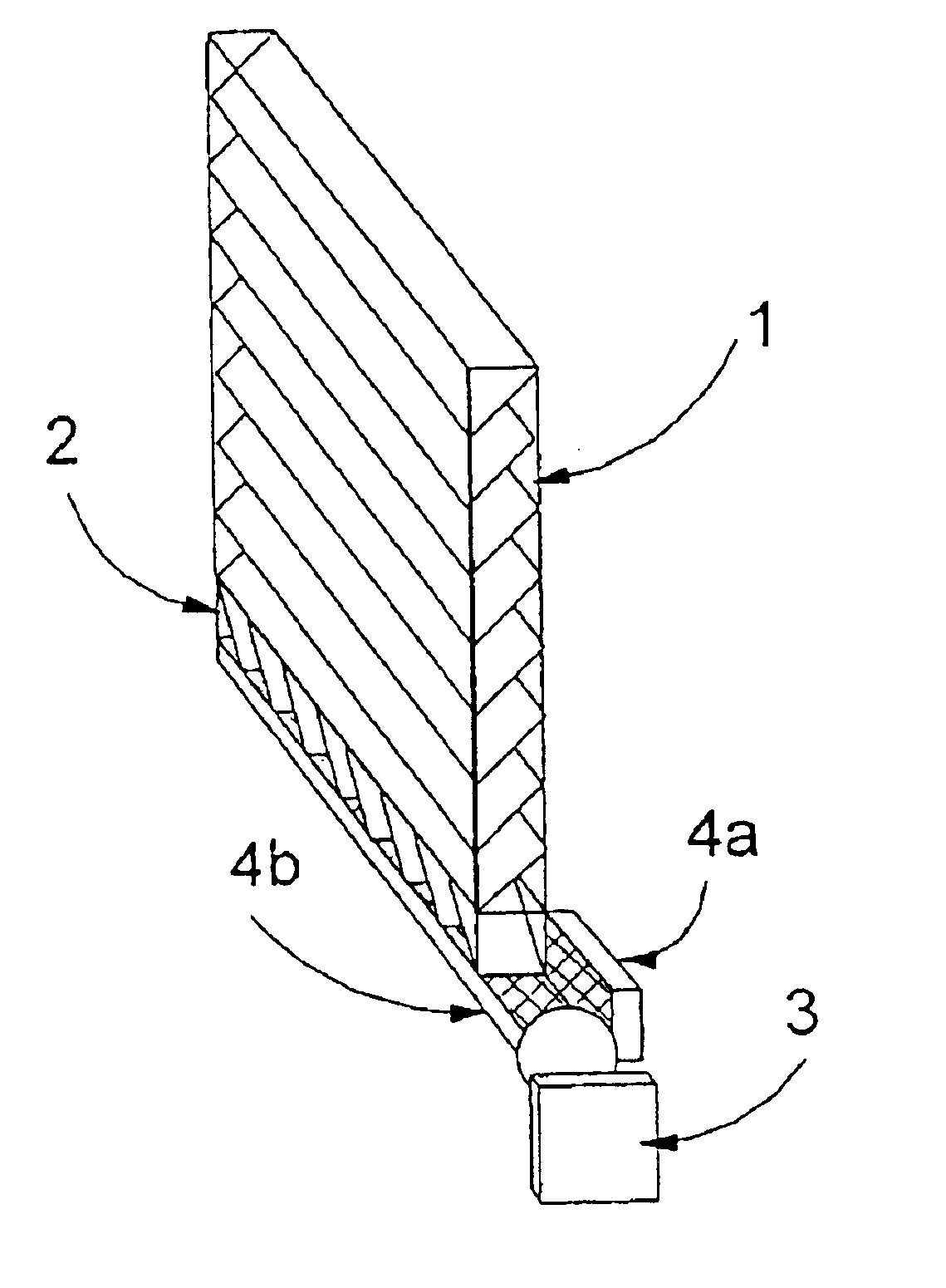
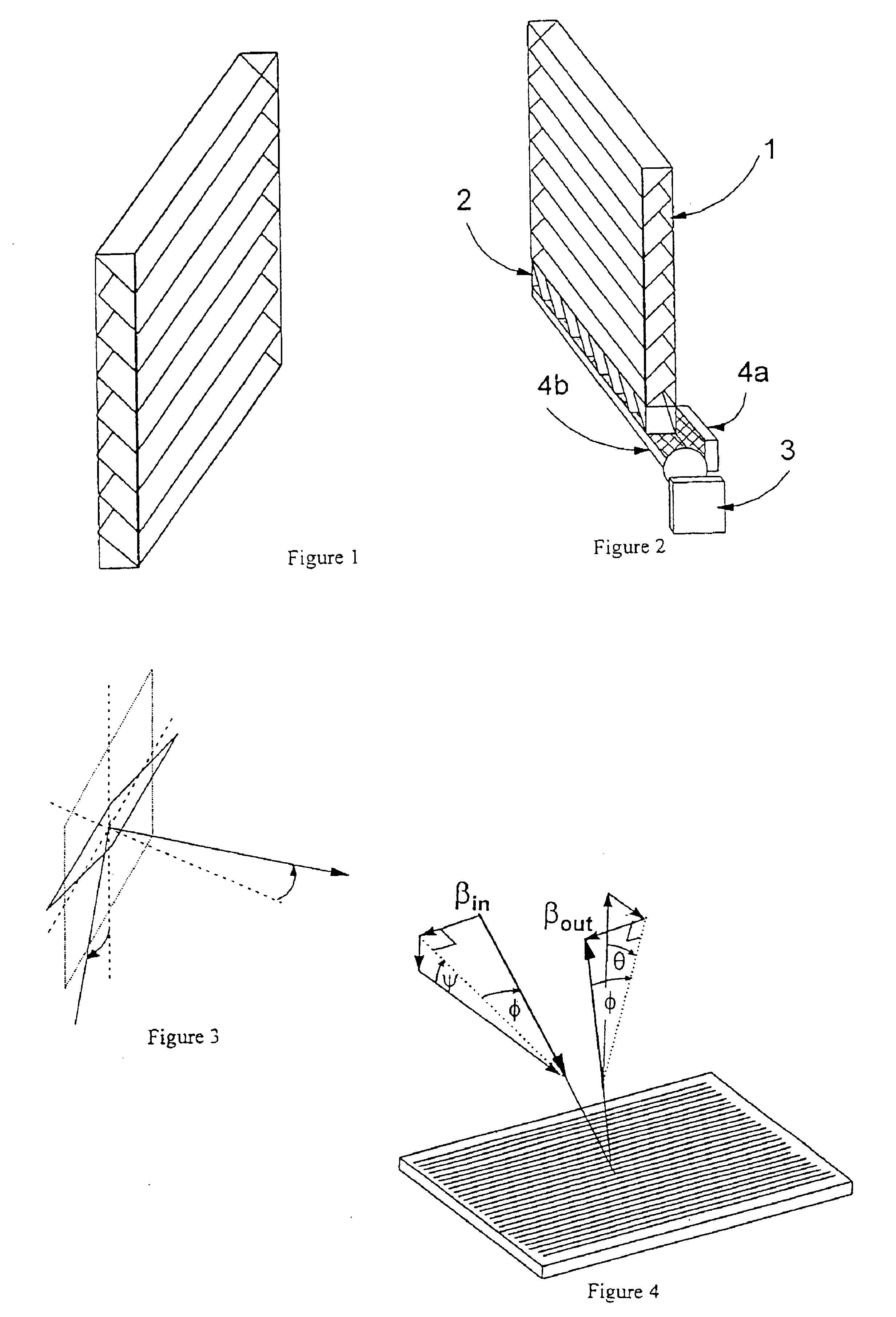
The transparent slab 1 shown in FIG. 1 is made by cutting approximately 0.5 mm thick sheets of highly transparent float glass into rectangular strips, then laying them one on top of another and in parallel so that their long sides are all in the horizontal, but their short sides are all at 45° to the horizontal. The stack is suffused with glue of a refractive index chosen so that the dielectric interface between glue and glass is weakly reflecting, then the stack is polished into a cuboid slab with faces parallel to the edges of the glass strips.

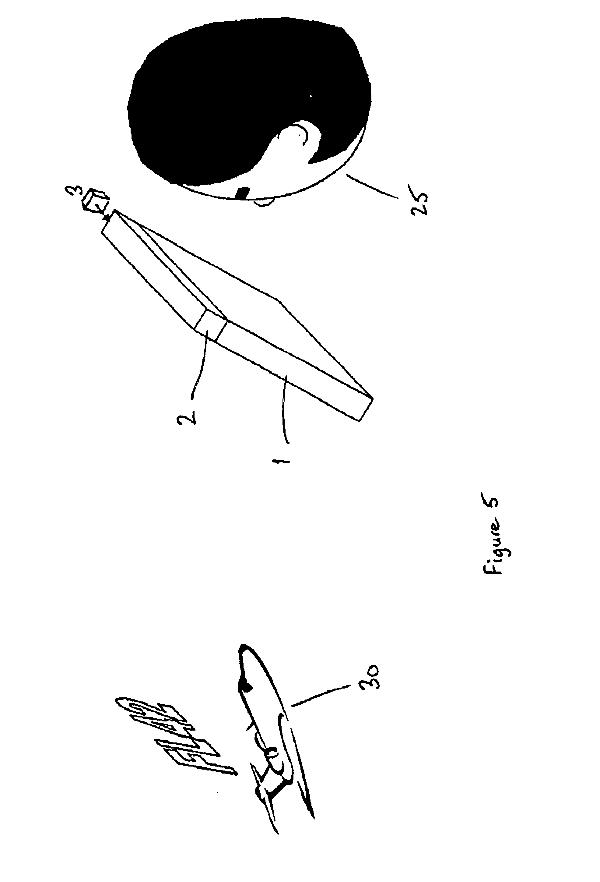
A transparent rod 2 is made in the same way as the transparent slab 1, except that the rod 2 has an approximately square cross-section corresponding to the thickness of the slab. FIG. 2 shows how the flat-panel projection display is assembled by focussing a video projector 3 into one end of the rod 2, then placing the rod 2 adjacent and parallel to the base of the transparent slab 1 with such an orientation that light from the video projecto...


PUM


Abstract

A flat-panel projection display comprises a transparent slab and integral area grating, a transparent rod with rectangular cross-section and integral linear grating, arranged along the edge of the slab, and a small video projector. The projector is arranged to direct a virtual image into the end of the rod, directly or via mirrors, the light travelling along the rod via total internal reflection. The linear grating diverts the light into the plane of the slab, and the area grating projects it out of the slab towards a viewer, so that the viewer sees an image at infinity.

Description

FIELD OF THE INVENTIONThis invention relates to the field of 3D displays, head-mounted displays and projection displays and is a way of making them flat.BACKGROUND OF THE INVENTIONProjection displays conventionally comprise a two-dimensional array of light emitters and a projection lens. The lens forms an image of the array at some plane in space, and if this imaging plane is far from the projection lens then the effect of the projection lens is to collimate light from any pixel on the two dimensional array.Projection displays are most commonly directed so that the image of the array falls on a large translucent screen, and a viewer looking at the screen will see a greatly magnified image of the picture on the two-dimensional array. But applications are becoming increasingly common in which small projection displays are mounted on the head of the viewer so that the projection display is directed towards the viewer's eye, and light collimated by the projection lens from a single pixe...

Claims


Application Information

Patent Timeline
Patent Type & Authority Patents(United States)
IPC IPC(8): G02B27/01G02B27/22G02B27/00G03B21/00H04N13/04
CPCG02B27/0081G02B27/2214G02B27/0101G02B2027/0123G02B30/27
Inventor TRAVIS, ADRIAN ROBERT LEIGH
Owner MICROSOFT TECH LICENSING LLC
Why Eureka
Try Eureka