Wire lead guide and method for terminating a communications cable

a technology of lead guide and communication cable, which is applied in the direction of electrically conductive connection, coupling device connection, electrical apparatus, etc., can solve the problems of significant performance degradation, affecting performance, and severely affecting transmission performan

Active Publication Date: 2006-12-19
BELDEN CANADA ULC
View PDF11 Cites 30 Cited by
  • Summary
  • Abstract
  • Description
  • Claims
  • Application Information

AI Technical Summary

Problems solved by technology

In particular, the cable termination on the back of the connector is an important factor and the conduction of an installation in a casual manner can lead to a significant degradation of performance.
Crosstalk gives rise to undesirable interference which can severely affect transmission performance.
Crossing of wires can arise due to a number of reasons including failure to take appropriate care during installation or physical forces brought to bear on the cable or connector, for example during the installation of other cables.
Additionally, failure to take appropriate care when stripping the jacket from the length of cable as well as untwisting the twisted pairs can create a loop which can also affect performance.
Therefore, installation of the cable on the back of each connector becomes very sensitive to the manner in which the installation is carried out by the installer.

Method used


Image

  • Wire lead guide and method for terminating a communications cable
  • Wire lead guide and method for terminating a communications cable
  • Wire lead guide and method for terminating a communications cable

Examples


Embodiment Construction

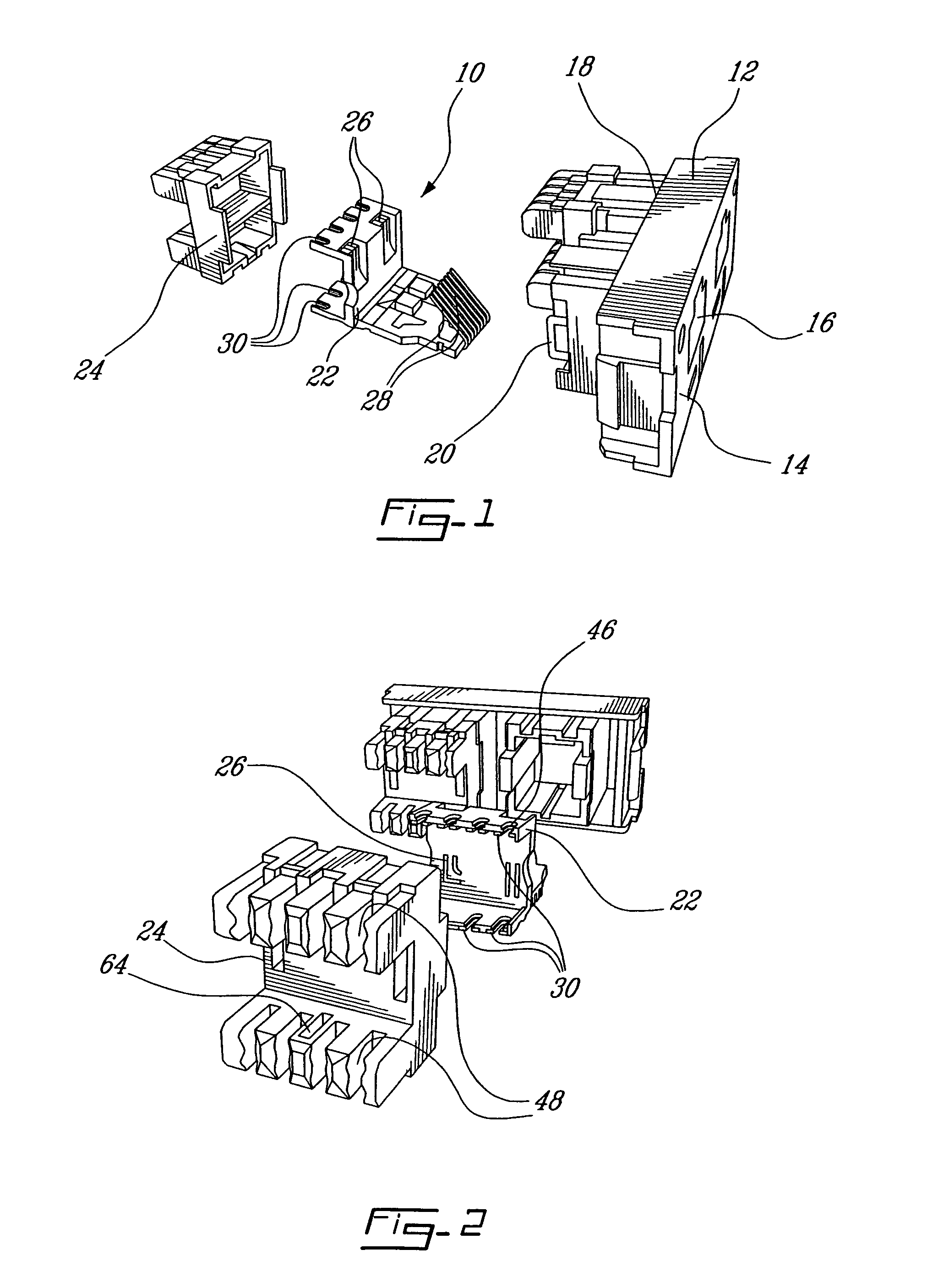
[0027]Referring to FIG. 1, a connector assembly, generally referred to using the numeral 10, for insertion into a patch bay or receptacle cover (both not shown) is disclosed. The connector assembly 10 is typically comprised of a front plate 12 having moulded into its front side 14 a socket 16 into which a patch cable having the requisite connector plug (both not shown) can be inserted. The front plate is typically manufactured from a dielectric material which is easily cast such as plastic. Moulded into the rear side 18 of the front plate 12 is a receptacle 20 for receiving a snap in interconnection module 22 and snap on cover 24.

[0028]Note that although the socket 16 in the present illustrative embodiment is adapted to receive an RJ-45 type plug, sockets as in 16 having shapes adapted to receive other types of connectors are also within the scope of the present invention. Additionally, the connector assembly 10 could also be integrated into a patch panel (not shown) or form part of...


PUM

PropertyMeasurementUnit
lay lengthsaaaaaaaaaa
lengthaaaaaaaaaa
transmission frequenciesaaaaaaaaaa

Abstract

A method for terminating a telecommunications cable where the cable comprises a plurality of twisted pairs of wires. The method comprises the steps providing an interconnection module comprising a pair of contacts for each of the twisted pairs, aligning the end portions and interconnecting each of the aligned end portions with a corresponding pair of conductive contacts. The aligning step comprises arranging the end portions such that when connected to the contact pairs, the twisted pairs remain uncrossed.A wire lead guide for isolating the end portions of a plurality twisted pairs of wires an a connector assembly using the same. The guide comprises a guide body and a plurality of non-intersecting passageways through the body. Each of the passageways is comprised of an entrance and an exit. The end portions of one of the twisted pairs are inserted through a corresponding one of the passageways. The passageways isolate the twisted pairs of wires from one another.

Description

PRIORITY[0001]This application claims priority to U.S. Provisional App. No. 60 / 472,779, filed May 23, 2003.FIELD OF THE INVENTION[0002]The present invention relates to a wire lead guide which serves as a guide for wires between the end of the cable and a connector and a method for terminating a communications cable. In particular, the present invention relates to wire lead guide for arranging the individual twisted pairs of wires exiting the end of a telecommunications cable, their connection to a connector and the method of use of the wire lead guide in order to improve performance of the cable / connector assembly.BACKGROUND[0003]The development of the Category 6 standard (ANSI / TIA / EIA-568-B.2-1) and its subsequent wide acceptance by the telecommunications industry has raised the transmission requirements for electrical signals in telecommunications cables to a higher level than ever. Category 6 is a performance classification for twisted pair cables, connectors and systems which is...

Claims


Application Information

Patent Timeline
Patent Type & Authority Patents(United States)
IPC IPC(8): H01R24/00H01R4/24H01R9/22H01R9/24
CPCH01R13/6463Y10S439/941Y10T29/49169Y10T29/49195Y10T29/49201Y10T29/49194Y10T29/49174Y10T29/49123
Inventor QUENNEVILLE, ALAINBOHBOT, MICHELTAZBAZ, ANTOINE
Owner BELDEN CANADA ULC
Why Eureka
Try Eureka