Flow-reversing valve

a flow-reversing valve and valve body technology, applied in the field of valves, can solve problems such as the problem of dimensioning of the valve, and achieve the effects of reducing the forces between the flow splitter and the control element, improving sealing, and reducing frictional forces

Inactive Publication Date: 2006-12-26
KSB AG
View PDF11 Cites 15 Cited by
  • Summary
  • Abstract
  • Description
  • Claims
  • Application Information

AI Technical Summary

Benefits of technology

[0007]It is an object of the present invention to provide a changeover device, in particular for large reverse osmosis installations and the like, with which large flows of fluid can be distributed between different pressure exchangers in a straightforward and fault-free manner.
[0008]The solution to this program provides for a flow splitter provided with a plurality of transfer paths to be arranged within the housing, for openings of the transfer paths to be arranged at two axial ends and on the circumference of the flow splitter, and for a rotating, disk-like control element to be arranged in a sealing manner at each end of the flow splitter. Thus, in the case of such fluid flows which are to be controlled and which change direction periodically, a changeover with few pressure surges can be achieved.

Problems solved by technology

However, this valve is suitable only for small reverse osmosis installations, since the flow cross sections within the valve are approximately the same size as the flow cross sections of the ducts to be filled.
In large installations and the fluid columns to be displaced therein, and as a result of the forces necessitated thereby, a considerable problem of dimensioning the valve arises.

Method used


Image

  • Flow-reversing valve
  • Flow-reversing valve
  • Flow-reversing valve

Examples


Embodiment Construction

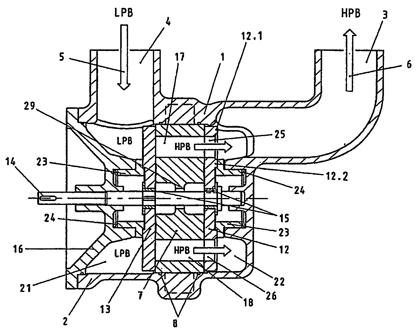
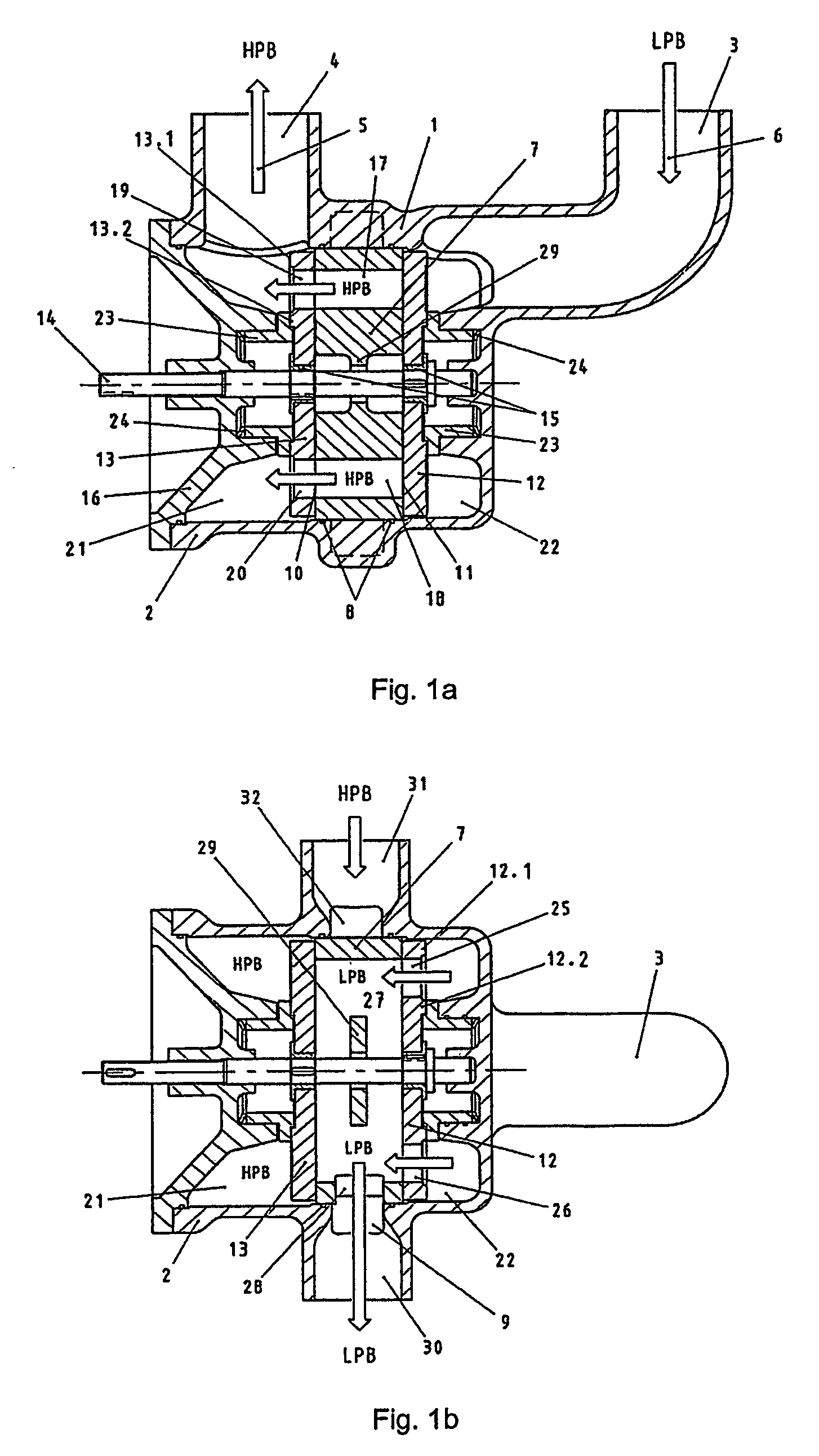
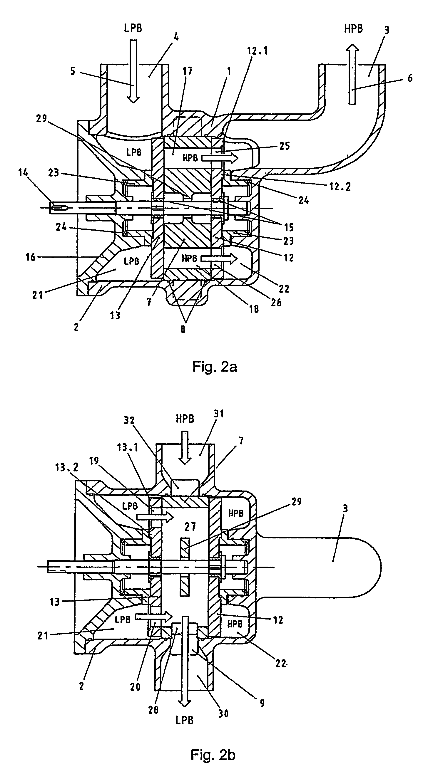
[0028]A Valve 1 is shown in section in FIG. 1a. The housing 2 has two connections 3, 4 through which a connection to the tube chambers (not shown) of a pressure exchanger system is made. An alternating exchange of a fluid which flows in under high pressure and flows back at lower pressure is effected via the connections 3, 4. Arrows 5, 6 show the respectively prevailing flow directions. The distance between the connections 3, 4 is chosen in accordance with the distance between tubular chambers to be connected thereto. This integration of the connections 3, 4 into the housing 2 avoids unnecessary additional sealing points.

[0029]Arranged inside the housing 2 is a flow splitter 7 which, in the illustrative embodiment shown, is configured as a separate insert. It can equally well be configured as a single-piece component with the housing 2. The flow splitter 7, formed as an insert here, is sealed off with respect to the housing 2 with the aid of seals 8. In the region of the circumferen...


PUM


Abstract

A valve for switching fluid paths, particularly for pressure exchanger installations with tubular chambers through which fluid flows in an alternating manner, including a rotatable closing element (12, 13) provided with a motorized drive shaft (14) and arranged inside a housing (2) having a plurality of connections (3, 4) for connecting lines leading to a pipe system and to a respective end of at least one pressure exchanger. Another end of each pressure exchanger is connected through a valve arrangement to a second pipe system. A splitter (7) provided with a plurality of overflow paths (17, 18, 27) is arranged inside the housing (2); mouths of the overflow paths are located on two axial end faces (10, 11) and on the circumference of the splitter (7), and a rotatable, disk-shaped control element (12, 13) is arranged in a sealing manner at each end face of the splitter (7).

Description

CROSS REFERENCE TO RELATED APPLICATIONS[0001]This application is a continuation of international patent application no. PCT / EP2004 / 000987, filed Feb. 4, 2004 designating the United States of America and published in German as WO 2004 / 081431 on Sep. 23, 2004, the entire disclosure of which is incorporated herein by reference. Priority is claimed based on Federal Republic of Germany patent application no. DE 103 10 662.6, filed Mar. 12, 2003.BACKGROUND OF THE INVENTION[0002]The present invention relates to a valve, particularly for pressure exchanger installations comprising pressure exchangers with tubular chambers through which an alternating flow takes place, a rotatable closing element arranged inside a housing, the housing having a plurality of connections for connecting lines, the housing being connected to a first pipe system and in each case one end of at least one pressure exchanger, a respective other end of each pressure exchanger being connected through a valve to a second...

Claims


Application Information

Patent Timeline
Patent Type & Authority Patents(United States)
IPC IPC(8): F16K11/00B01D61/06B01D61/10F16K11/074
CPCB01D61/06B01D61/10F16K11/074F16K11/0746Y10T137/86863Y10T137/5689Y10T137/86823
Inventor BAUMGARTEN, SVENBROSS, STEPHENBRECHT, BERNHARDBRUHNS, UWEELLEGAARD, MOGENSFLAK, STEFANJAEGER, CHRISTOPHKOCHANOWSKI, WOLFGANGKNOEBL, WILTRUD
Owner KSB AG
Why Eureka
Try Eureka