
Terminal block jumper

a technology of terminal block and jumper, which is applied in the direction of electrical apparatus, electrical discharge tubes, coupling device connections, etc., can solve the problems of service person injury and time-consuming process, and achieve the effect of minimizing the exposure of the utility service person

Inactive Publication Date: 2006-12-26
EKSTROM INDS
View PDF16 Cites 16 Cited by
  • Summary
  • Abstract
  • Description
  • Claims
  • Application Information

AI Technical Summary

Benefits of technology

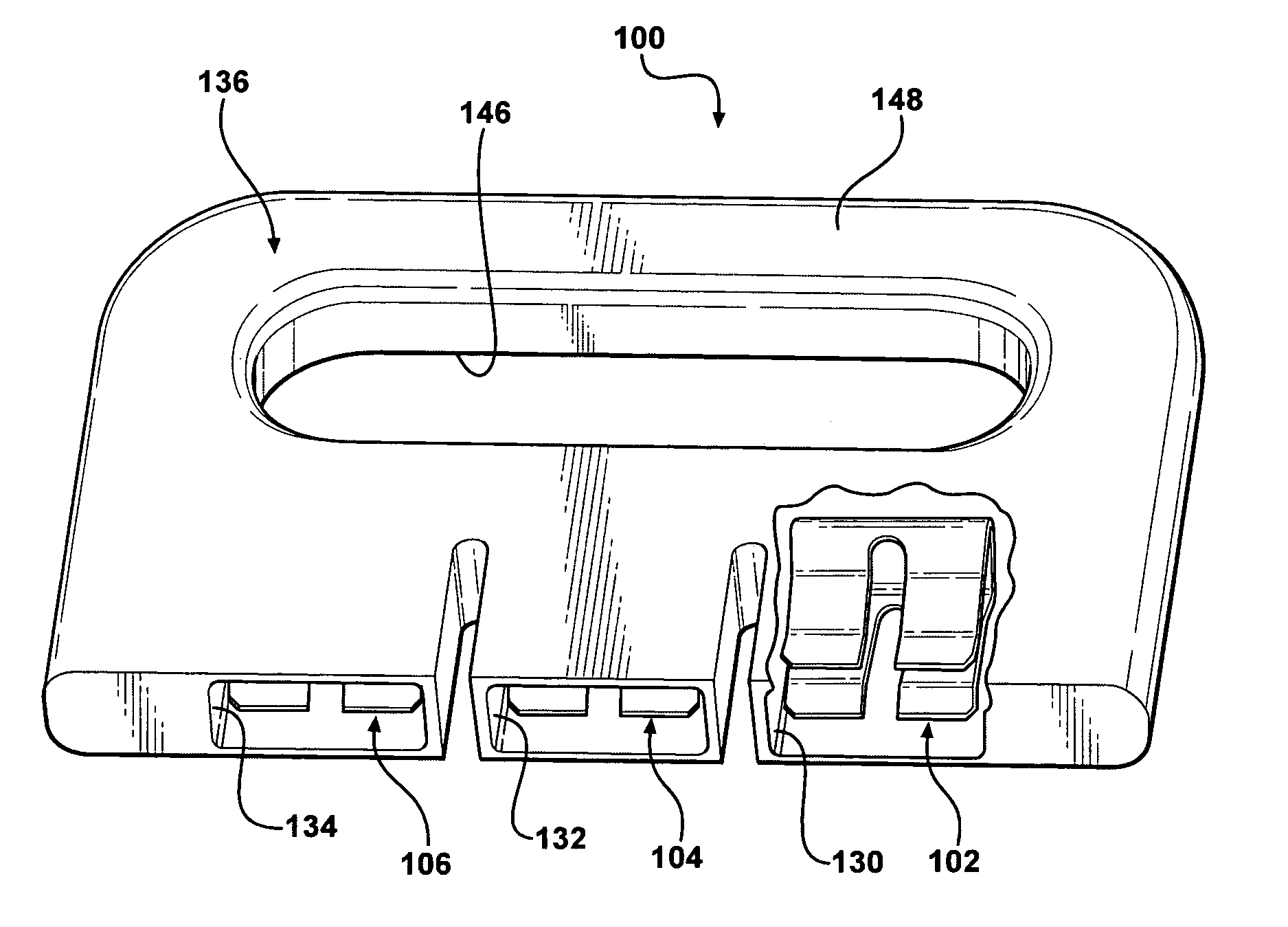
[0015]A hand grip means may also be formed in the body for facilitating movement of the jumper. The hand grip means may include an opening in the body for receiving a user's hand and an adjacent bar.
[0019]The terminal block jumper provides a safe and quickly installable and removable jumper to enable a meter to be safely removed from a socket or housing and a new meter installed while minimizing the exposure of the utility service person to the danger of contact with live electrical power. The terminal block jumper is also mountable on and removable from the threaded studs in the electrical service apparatus without damaging the studs.

Problems solved by technology

This is a time consuming process.
The installation and removal of the jumpers poses a safety hazzard to the utility service person since the meter is installed and removed from the socket under live power conditions.
Accidental dropping of the wrench or nut driver can cause the wrench or nut driver to fall into the socket and possibly short across the bus bars creating a hazardous short which could damage the socket and cause injury to the service person.

Method used


Image

  • Terminal block jumper
  • Terminal block jumper
  • Terminal block jumper

Examples


Embodiment Construction

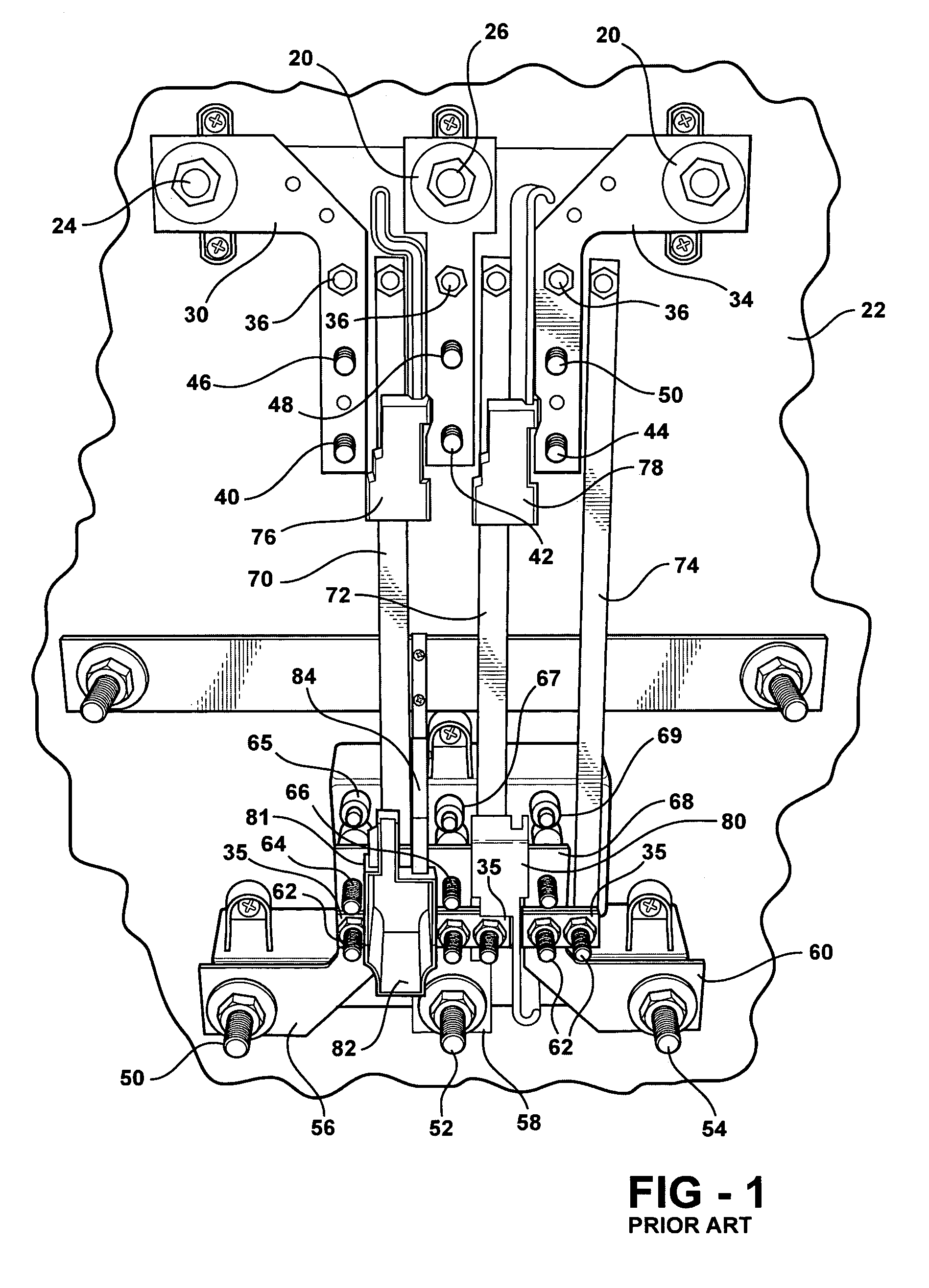
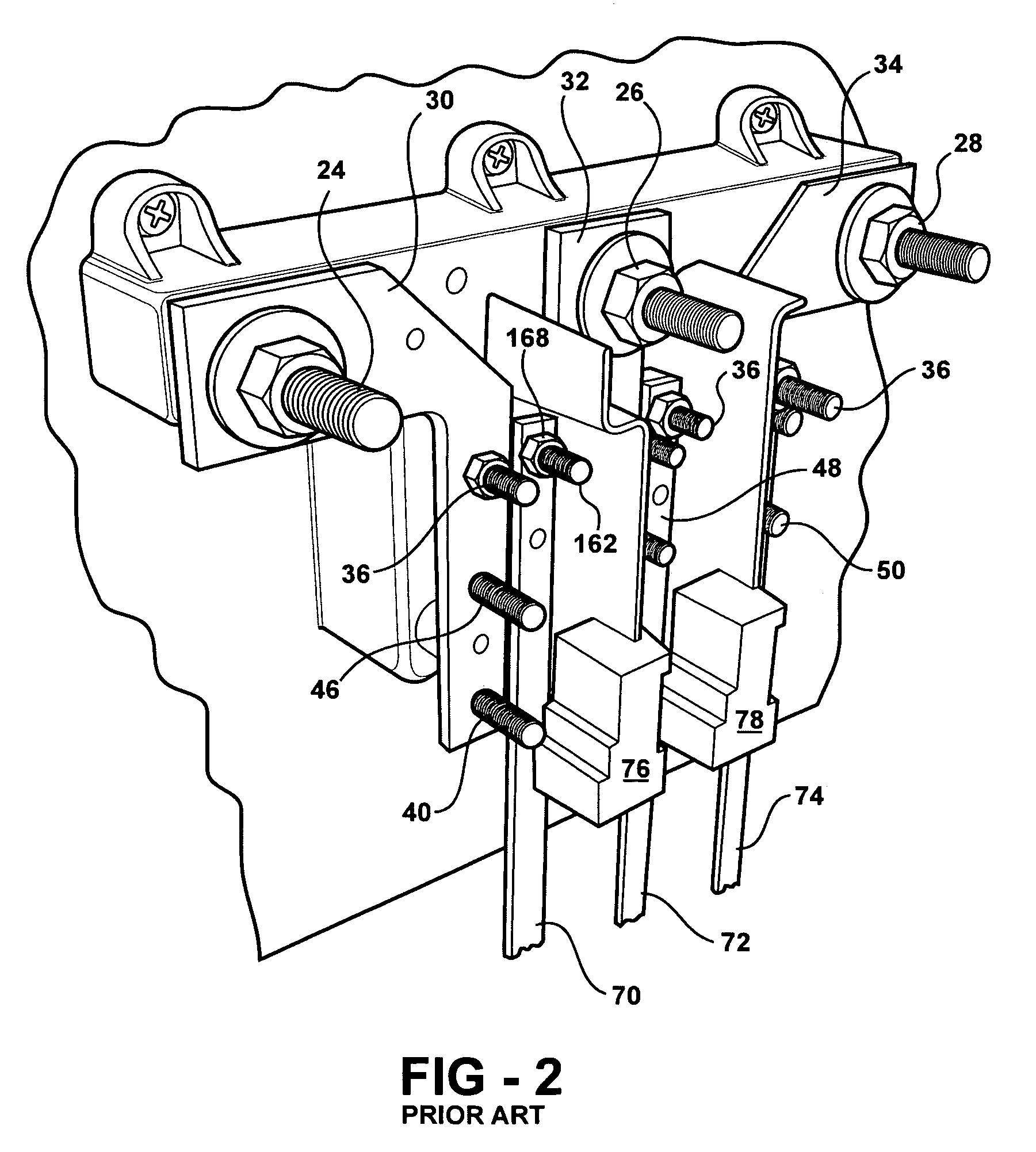
[0033]For clarity in understanding the features and advantages of the present watthour meter socket adapter, a description will be first presented with reference to FIGS. 1–4 of a prior art K-series watthour meter socket designed for receiving a K-series watthour meter.

[0034]As shown in FIGS. 1–4, a K-series meter socket, which generally in the form of a closed housing having a removable cover, as described hereafter, includes a base plate 22 on which three line terminals 24, 26 and 28 for the exemplary three-phase power application are mounted. It will be understood that only two terminals, such as terminals 24 and 26, are necessary for single phase applications. The terminals 24, 26 and 28 are mounted on the base plate 22. The terminals 24, 26 and 28 provide a connection point for power distribution line conductors, not shown, which are mounted and secured in place over the terminals 24, 26 and 28.

[0035]Individual plate-like line bus bars 30, 32 and 34 are connected at one end to ...


PUM


Abstract

An electrically insulated body carries one of more jaw members which are mountable over threaded terminals in a meter socket to provide a bypass connection between line and load socket terminals to enable a watthour meter to be removed and reinstalled relative to the socket. In another aspect, the jaw members are coupled to an electrically conductive member. A handle extends from the conductive member.

Description

BACKGROUND[0001]The present invention relates, in general, to electrical power metering apparatus and, specifically, to electrical watthour meters and watthour meter sockets.[0002]In the electric utility industry, plug-in, socket-type watthour meters are commonly employed to measure electric power consumption at a residential or commercial building establishment. A socket is mounted on a wall of the residence or building and contains terminals which are connected to electric line and electric load conductors. The terminals are also connected to internal conductors within the socket which extend to jaw contacts positioned to receive the blade terminals of a plug-on watthour meter to complete an electric circuit through the watthour meter between the line and load terminals and the conductors.[0003]One type of meter socket has a ring-type cover which includes an outwardly projecting, annular mounting flange surrounding an opening in the cover through which the blade terminals of a wat...

Claims


Application Information

Patent Timeline
Patent Type & Authority Patents(United States)
IPC IPC(8): H01R31/08
CPCH01R13/112H01R31/08
Inventor ROBINSON, DARRELLLOEHR, KARL R.
Owner EKSTROM INDS
Learn More