High efficiency multi-spectral optical splitter

Inactive Publication Date: 2006-12-26
THE BOEING CO
View PDF28 Cites 31 Cited by
  • Summary
  • Abstract
  • Description
  • Claims
  • Application Information

AI Technical Summary

Benefits of technology

[0006]In a first preferred embodiment, the present invention provides a hexagonal wave guide. The hexagonal guide homogenizes a light wave that has an initial, non-uniform profile (i.e. an intensity distribution) to a wave with a uniform, or “top hat,” distribution as will be herein described. The source of the light may be an optical fiber or any other light producing or emitting device. Further, a bundle of optical fibers may be optically coupled to the output of the guide so as to accept the light with the homogenized profile. Since the light coupled into the bundle of fibers has a top hat profile, each fiber receives approximately the same portion of the intensity of the original light wave. Thus, the guide of the present invention may be employed in a fiber optic splitter. A coupler may also be provided to align the light source and the wave guide. The mount may also align the wave guide and the output bundle as well. Thus, mis-alignments of as much as 2 degrees and 10 degrees at the source and the output, respectively, may be tolerated without significant light loss associated with the splitter.

Problems solved by technology

For illumination systems, in particular, the efficiency of the splitter is of importance because light loss associated with the splitter becomes unavailable for the satisfaction of the illumination demands.

Method used


Image

  • High efficiency multi-spectral optical splitter
  • High efficiency multi-spectral optical splitter
  • High efficiency multi-spectral optical splitter

Examples


Embodiment Construction

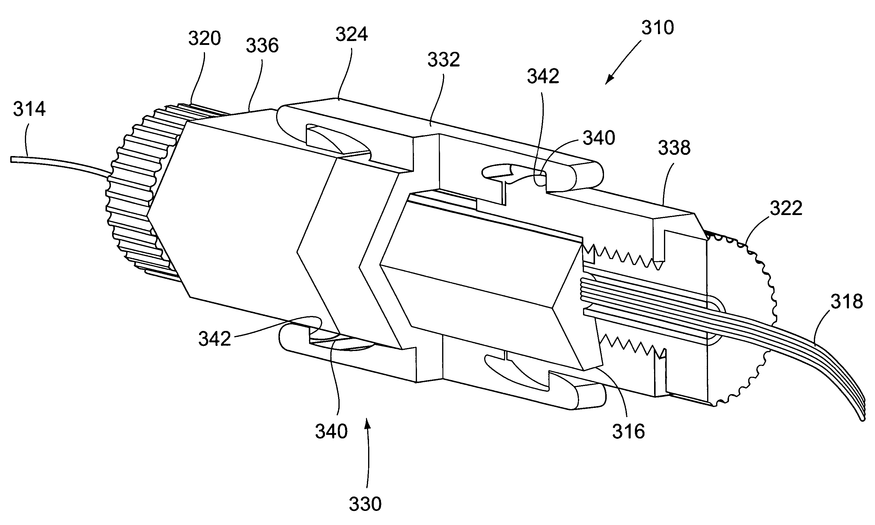
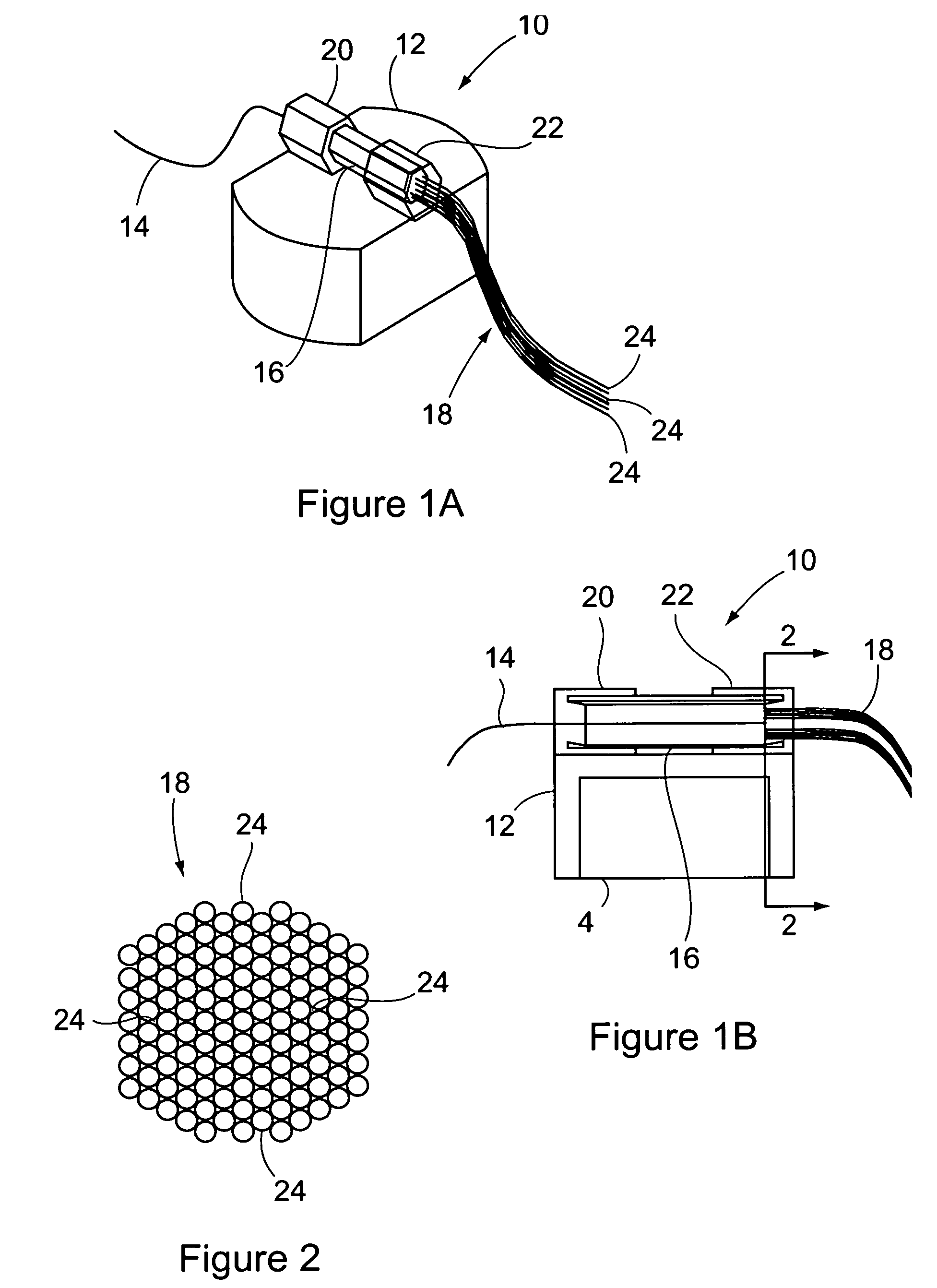
[0016]Referring to the accompanying drawings in which like reference numbers indicate like elements, FIG. 1 illustrates a preferred optical splitter 10 constructed in accordance with the principals of the present invention.

[0017]FIG. 1 also illustrates a coupler 12, an optical source 14, a wave guide 16, an output fiber bundle 18, a source bracket 20, and an output bundle bracket 22 of the splitter 10. The coupler 12 includes the brackets 20 and 22 that align the source 14 and the output fiber bundle 18 with the guide 16. As shown, the guide 16 has a cross section that defines a polygon (e.g. a hexagon). FIG. 2 illustrates the output fiber bundle 18 of FIG. 1 as seen along the line 2—2. As shown, the output bundle 18 may have a cross section generally corresponding to that of the guide 16. Further, the output bundle 18 includes a plurality of fibers 24 packed together to approximate the hexagonal cross section of the guide 16. The spacing between the individual fibers 24 is also pre...


PUM


Abstract

An optical wave guide. The guide includes a body with a cross section that defines a polygon, preferably a hexagon. The proximal end of the body optically couples to an optical source (e.g. an optical fiber or light source) with an initial distribution. The wave travels through the body to the distal end whereby the distribution becomes a top hat distribution. In another preferred embodiment a bundle of optical fibers is coupled to the distal end. Additionally, the guide may include a coupler to align the source and the bundle with the body. In yet another preferred embodiment, the length of the body is at least about 6 times the width of the cross section. In another preferred embodiment, a method of splitting a wave is provided. The method includes passing an electromagnetic wave through a wave guide with a hexagonal cross section.

Description

FIELD OF THE INVENTION[0001]This invention relates generally to optical splitters and, more particularly, to optical splitters having the capability to split a single light source into a plurality of portions having approximately equal intensity.BACKGROUND OF THE INVENTION[0002]A need exists in both fiber optic telecommunications and fiber optic illumination systems to split light (i.e. electromagnetic waves) into numerous portions of equal intensity for transmission to different locations. In fiber optic communication systems, such splitting allows a signal to be fanned out to many different receivers. In illumination systems, such splitting allows a single source to illuminate numerous locations spread about the source at various distances and in various directions.[0003]For illumination systems, in particular, the efficiency of the splitter is of importance because light loss associated with the splitter becomes unavailable for the satisfaction of the illumination demands. Furthe...

Claims


Application Information

Patent Timeline
Patent Type & Authority Patents(United States)
IPC IPC(8): G02B6/10G02B6/28
CPCG02B6/2808
Inventor CIANCIOTTO, FRANKBUTLER, GEORGE
Owner THE BOEING CO
Why Eureka
Try Eureka