Strain sensor with fixing members

a technology of fixing members and strain sensors, which is applied in the field of strain sensors, can solve the problems of deteriorating and achieve the effect of improving detection accuracy and detection output accuracy of strain sensors

Inactive Publication Date: 2007-01-02
PANASONIC CORP
View PDF11 Cites 31 Cited by
  • Summary
  • Abstract
  • Description
  • Claims
  • Application Information

AI Technical Summary

Benefits of technology

[0012]The present invention is intended to provide a strain sensor which may assure the improvement of detection output accuracy without variation of the bending stress applied to the strain detecting element.
[0015]In this configuration, the first fixing member, the second fixing member and the detecting member are respectively press-fitted into the first fixing hole, the second fixing hole and the detecting hole. Accordingly, when an external force is applied to the detecting member, the respective end positions of the detecting member, the first fixing member, and the second fixing member which are in contact with the sensor substrate are free from positional shifting. Consequently, the bending stress applied to the strain detecting element is stabilized. Accordingly, the detection output accuracy of the strain sensor will be improved.
[0016]Thus, it is possible to obtain a strain sensor which may assure the improvement of detection accuracy without variation of the bending stress applied to the strain detecting element.

Problems solved by technology

As a result, the output accuracy of the strain sensor will be deteriorated.

Method used


Image

  • Strain sensor with fixing members
  • Strain sensor with fixing members
  • Strain sensor with fixing members

Examples


embodiment 1

(Preferred Embodiment 1)

[0031]The preferred embodiment 1 of the present invention will be described in the following with reference to FIG. 1 to FIG. 7.

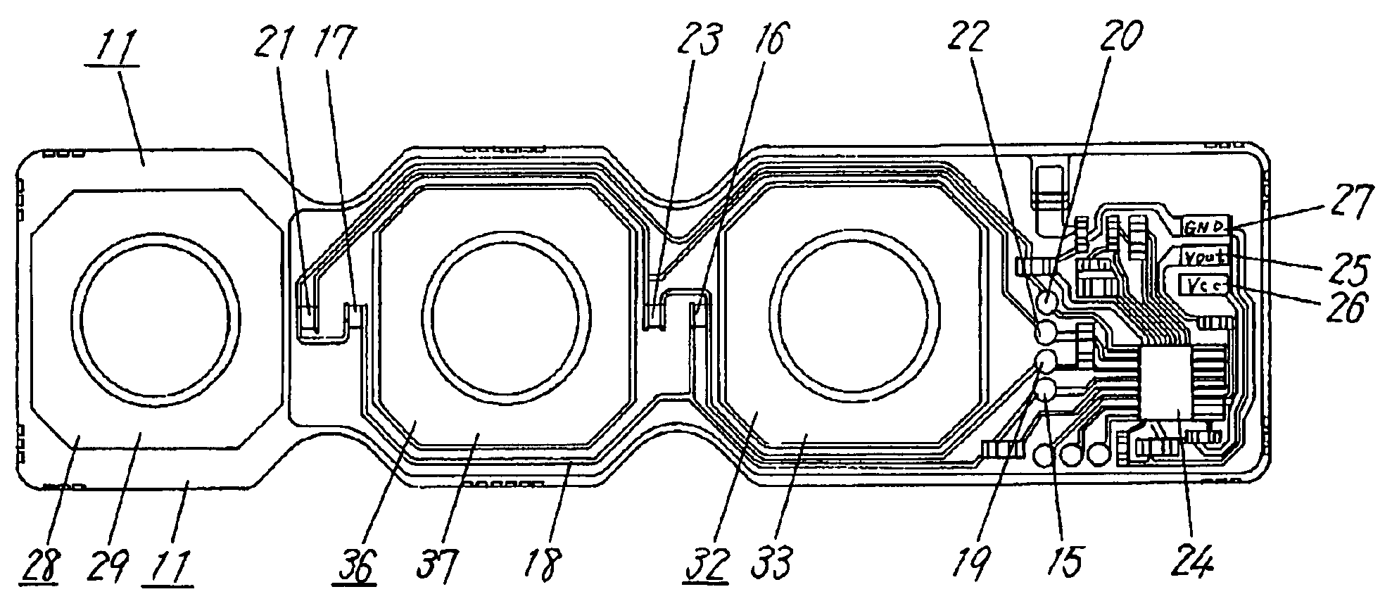
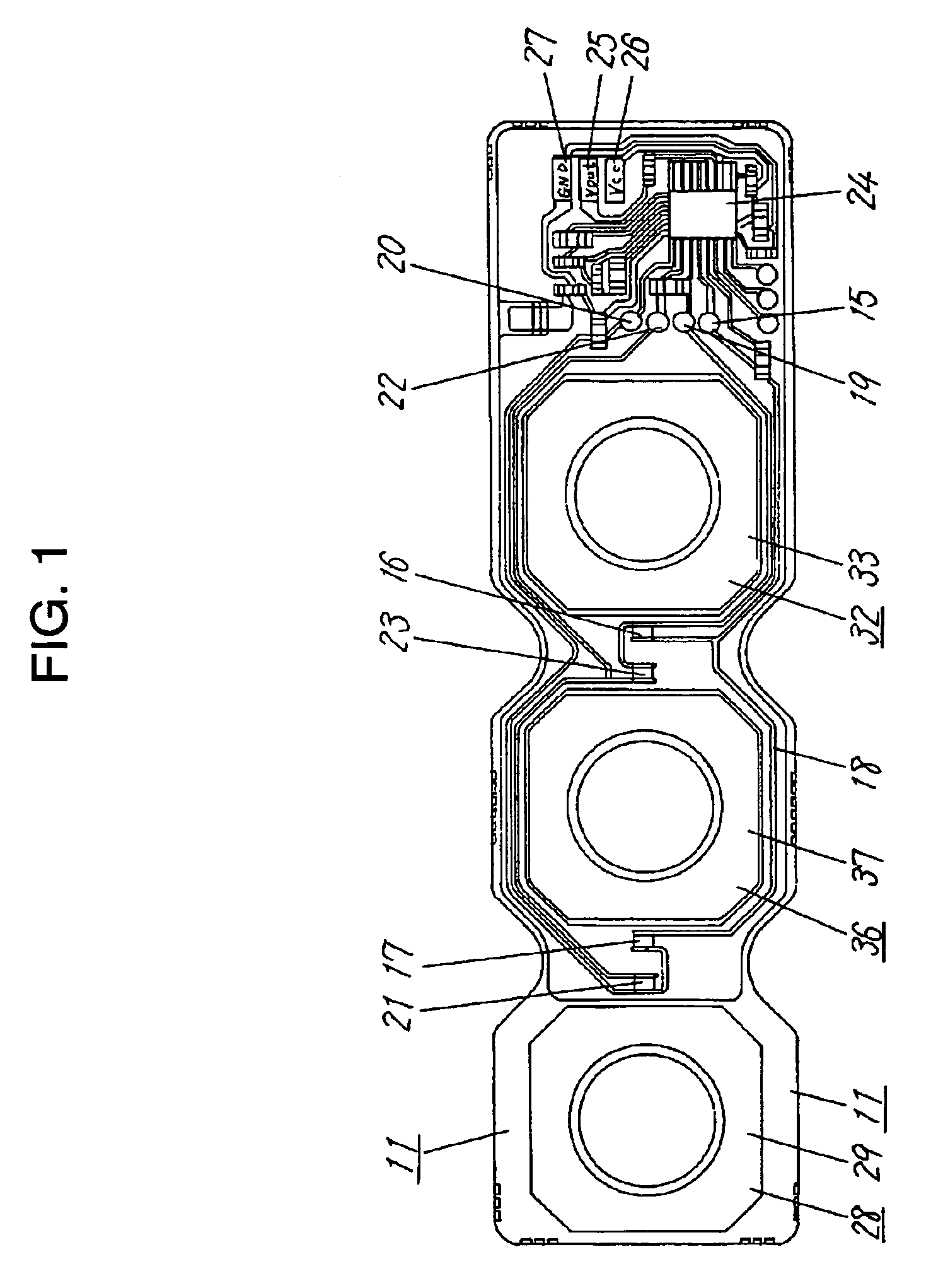
[0032]FIG. 1 is a top view of a strain sensor in the preferred embodiment 1 of the present invention.

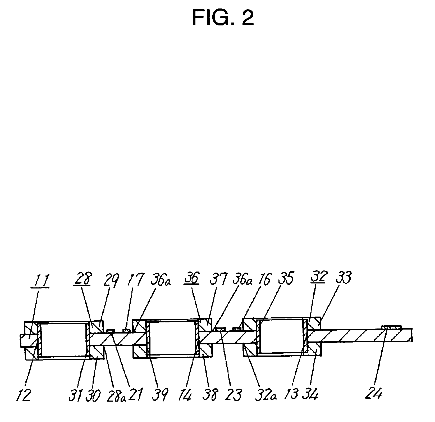
[0033]FIG. 2 is a side sectional view of the strain sensor.

[0034]FIG. 3 is a perspective view of a first upper washer in the strain sensor.

[0035]FIG. 4 is a perspective view of a first cylinder in the strain sensor.

[0036]FIG. 5 is a top view of a sensor substrate in the strain sensor.

[0037]FIG. 6 is a sectional view showing the structure of a locking means for locking a first fixing member to a sensor substrate of the strain sensor.

[0038]As shown in FIG. 5, sensor substrate 11 is provided with first fixing hole 12 ranging from top to bottom at one end, second fixing hole 13 ranging from top to bottom at the other end, and detecting hole 14 ranging from top to bottom at the center thereof.

[0039]Also, first fixing hole 12, second fixing...

embodiment 2

(Preferred Embodiment 2)

[0098]The preferred embodiment 2 will be described in the following with reference to FIG. 8 to FIG. 12.

[0099]FIG. 8 is a top view of a strain sensor in the preferred embodiment 2 of the present invention.

[0100]FIG. 9 is a side sectional view of the strain sensor.

[0101]FIG. 10 is a perspective view of a first upper washer of the strain sensor.

[0102]FIG. 11 is a top view of a sensor substrate of the strain sensor.

[0103]FIG. 12 is a sectional view showing the structure of a locking means for locking a first fixing member to the sensor substrate of the strain sensor.

[0104]Those having the same configurations as in the preferred embodiment 1 of the present invention are given the same reference numerals, and the description is omitted.

[0105]As shown in FIG. 8 to FIG. 12, first fixing member 41, second fixing member 45 and detecting member 50 of the strain sensor in the preferred embodiment 2 are configured as described in the following.

[0106]First fixing member 4...


PUM

PropertyMeasurementUnit
weightsaaaaaaaaaa
inner diametersaaaaaaaaaa
outer diameteraaaaaaaaaa

Abstract

A strain sensor improved in detection accuracy without variation of bending stresses applied to the strain detecting element. The sensor substrate has a first fixing hole at one end and a second fixing hole at the other end, a detecting hole at the center, and at least one strain detecting element on the upper surface or lower surface thereof. The first fixing member is press-fitted into the first fixing hole. The second fixing member is press-fitted into the second fixing hole. The detecting member is press-fitted into the detecting hole. Further, when an external force is applied to the detecting member, strain generated due to the positional shift of the detecting member is detected by the strain detecting element with respect to the first fixing member and the second fixing member.

Description

[0001]This application is a U.S. National Phase Application of PCT International Application PCT / JP02 / 09375.TECHNICAL FIELD[0002]The present invention relates to a strain sensor for detecting strain generated in a sensor substrate due to external forces produced by weights of men and vehicles such as automobiles by means of strain detecting elements mounted on the sensor substrate.BACKGROUND ART[0003]As a conventional strain sensor of this type, the one disclosed in the microfilm of Utility Model H4-265 (Japanese Laid-open Utility Model H5-57605) is well-known.[0004]A conventional strain sensor will be described in the following with reference to the drawings.[0005]FIG. 13 is a perspective view of a conventional strain sensor.[0006]In FIG. 13, sensor substrate 1 made of metal has first fixing hole 2 at one end and second fixing hole 3 at the other end, on which is disposed strain detecting sensor 4 having a thin gauge for detecting strain in a lengthwise direction.[0007]Also, strain...

Claims


Application Information

Patent Timeline
Patent Type & Authority Patents(United States)
IPC IPC(8): G01B7/16G01L1/22
CPCG01L1/2206
Inventor MATSUURA, AKIRAUEDA, SHINJIROOTOBE, TOSHIROKOBAYASHI, YASUNOBUOMOTO, KATSUHIKOMATSUKAWA, YASUNORIMOTOFUSA, TOSHIHARU
Owner PANASONIC CORP
Why Eureka
Try Eureka