Visual display system for displaying virtual images onto a field of vision

a visual display system and virtual image technology, applied in the field of textual and graphical information and images visual display systems, can solve the problems of reducing the efficiency of optics, increasing the cost of systems, and reducing the effect of attenuation or interference effects of coatings,

Inactive Publication Date: 2007-01-02
BIG BUDDY PERFORMANCE
View PDF22 Cites 112 Cited by
  • Summary
  • Abstract
  • Description
  • Claims
  • Application Information

AI Technical Summary

Problems solved by technology

The more efficient the optics, the more they tend to intrude on a viewer's field of vision; conversely, less efficient optics impose greater demands on the illumination source and drive up systems costs.
However, these optical coatings impart a tinted or colored appearance on optical components located between the viewer and the viewer's field of vision.
Attenuation or interference effects of the coatings can produce undesirable appearances.
Furthermore, government regulations restrict the degree of attenuation permissible, for example, for an automobile windshield, thereby limiting the extent to which the HUD design can use optical coatings directly mounted on a windshield.
While this approach extinguishes ghost images and employs a clear optic, the slats obscure the driver's field of vision to some degree.
Moreover, the multiple-slat optic is more difficult to manufacture than a single piece optic.
Furthermore, the wedged optic increases the amount of material needed for manufacture of the system, limiting system compactness and increasing system cost.
Conditioning of illumination sources is also needed for existing, optically clear HUD implementations, especially those employing Fresnel reflection and / or dielectric coatings, because illumination sources do not always yield desirable light characteristics at a point of viewing.
An automotive HUD producing display information in s-polarized light is therefore useless to a driver who is wearing polarized sunglasses.
Thus, current HUD devices suffer from field-of-vision obstruction, display attenuation, interference effects, and ghost images.

Method used


Image

  • Visual display system for displaying virtual images onto a field of vision
  • Visual display system for displaying virtual images onto a field of vision
  • Visual display system for displaying virtual images onto a field of vision

Examples


Embodiment Construction

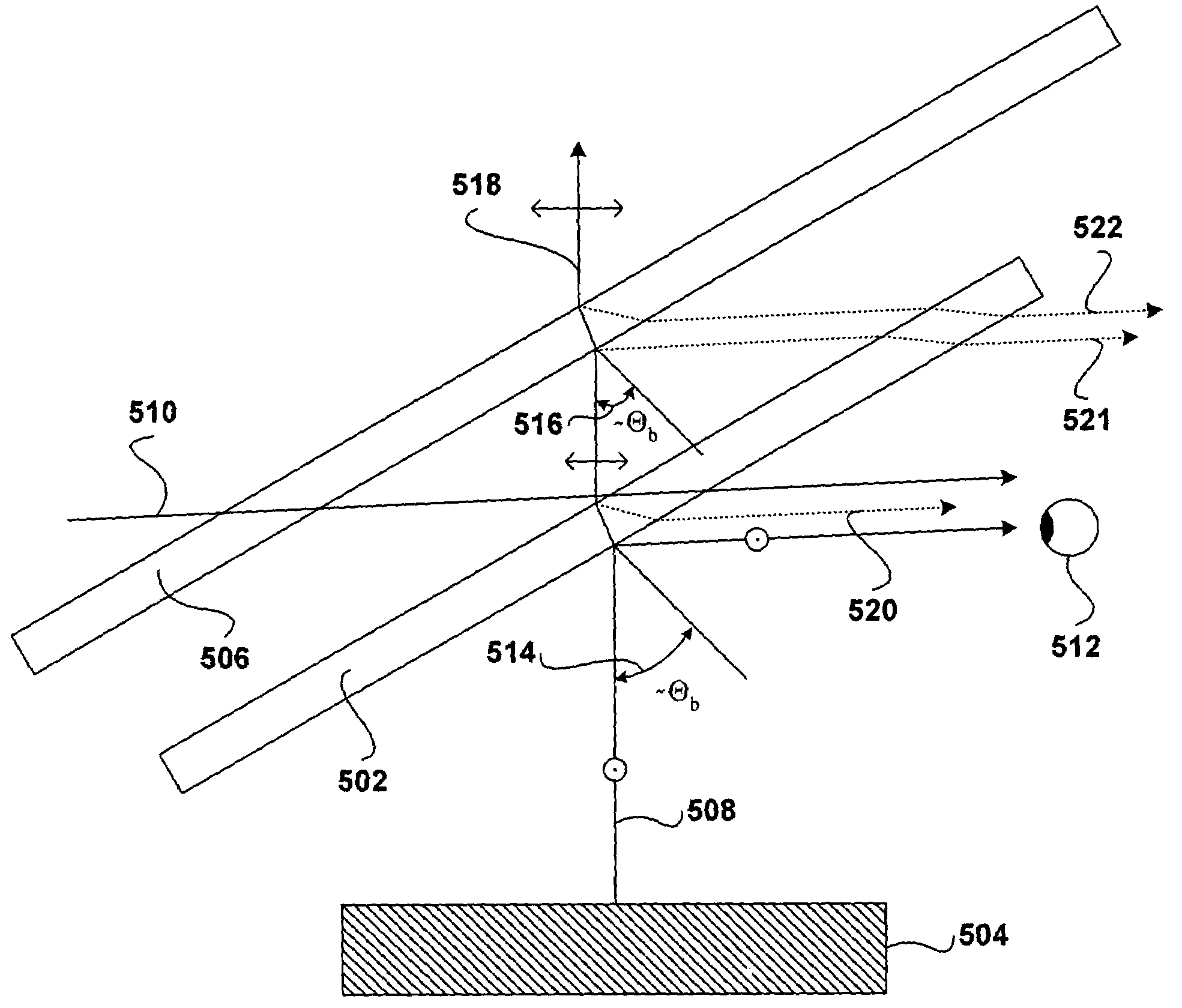
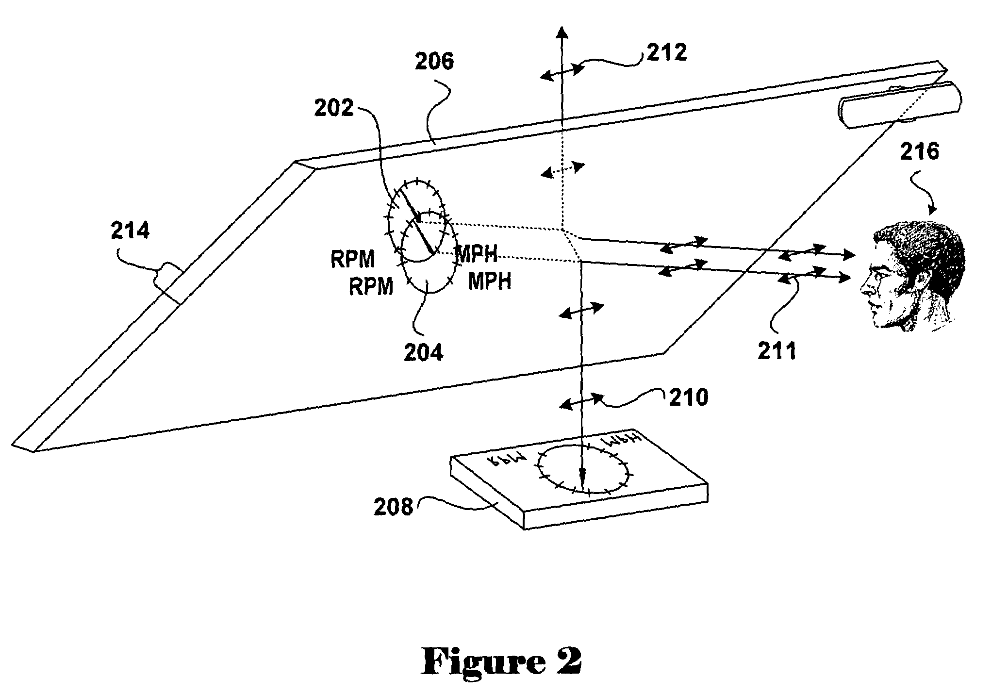
[0018]One embodiment of the present invention is the combination of a display projection system, imaging optics, a combiner that reflects displayed textual and graphical information, combining the light from the display projection system with light emanating from objects behind the combiner to superimpose the textual and graphical information onto a field of vision of a viewer, and, optionally, a vision-enhancing optic. These components together compose a transparent visual display system that presents textual and graphical information to a viewer in the viewer's field of vision. In other words, a viewer sees a roadway, airspace, or other scene with a virtual image of textual and / or graphical information superimposed within the field of vision, appearing partly transparent to the viewer.

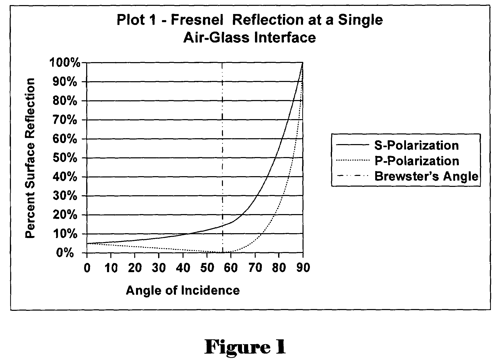
[0019]Three alternative combiner embodiments are disclosed. The disclosed combiner embodiments include: (1) a first combiner embodiment that utilizes an optic designed to optimize Fresnel reflection ...


PUM


Abstract

An optically transparent, ghost-free visual display system that superimposes a virtual image comprising graphical or textual information onto a field of vision. Embodiments of the visual display system utilize illumination and optical components that introduce a virtual image onto a field of vision while minimally obstructing and / or attenuating other objects within the field of vision. Embodiments of the visual display system can be used in numerous applications, including head-up displays (“HUDs”) for automotive, tracked and rail-mounted vehicles, marine, aerospace applications, see-through speech prompt displays, and see-through projection displays.

Description

TECHNICAL FIELD[0001]The present invention relates to visual display of textual and graphical information and images, and, in particular, to optically transparent visual display systems which superimpose ghost-free virtual images onto a field of vision with minimal obstruction of the field of vision.BACKGROUND OF THE INVENTION[0002]Head-up displays were originally developed, during the past 30 years, for displaying cockpit instruments to pilots, first in military, and now in both military and commercial aircraft. HUD technology has been more recently applied to additional applications. Various types of head-up display (“HUD”) systems have been produced, each designed to a unique set of requirements and each possessing certain advantages. HUDs are utilized, for example, to display vehicle sensory and navigation information. A HUD eliminates the need for a vehicle operator to divert his or her eyes from a field of vision, such as from the road, in an automobile application, in order t...

Claims


Application Information

Patent Timeline
Patent Type & Authority Patents(United States)
IPC IPC(8): G09G5/00G02BG02B5/30G02B27/00G02B27/01
CPCG02B27/0101G02B5/30G02B6/00G02B2027/012G02B27/0018
Inventor JENSON, BARTON JAMESBEAN, II, KENNETH EUGENEGEORGE, DAVID PAUL
Owner BIG BUDDY PERFORMANCE
Why Eureka
Try Eureka