
Pattern recognition for sheet metal part models

a technology of pattern recognition and part models, applied in the field of computer-aided design of sheet metal parts, can solve the problems of inaccurate and time-consuming direct comparison of 3d geometries of part shapes, inability to find similar parts, and inability to accurately compare parts. to achieve the effect of facilitating the search for similar parts

Inactive Publication Date: 2007-01-02
AMADA CO LTD
View PDF45 Cites 6 Cited by
  • Summary
  • Abstract
  • Description
  • Claims
  • Application Information

AI Technical Summary

Benefits of technology

This approach facilitates efficient pattern recognition and similarity searches, optimizing manufacturing processes by reusing legacy data and reducing the need for complete part designs, thereby improving cost estimation and part creation efficiency.

Problems solved by technology

None of the previous attempts, however, have succeeded in recognizing patterns of sheet metal part models to enable accurate comparison of sheet metal parts due to the hollowness or emptiness of sheet metal shapes.
In addition, directly comparing 3D geometries of part shapes is inaccurate and time consuming because such a geometric comparison of part shapes is very sensitive to size, orientations, etc. of shapes Thus, direct comparison often creates ambiguous search results.
However, the HAZAMA et al. system does not recognize patterns of sheet metal shapes and thus only searches by text such as “part name”, “updated date”, “material name”, “machine name,” etc.
Moreover, the input of search criteria in prior systems is inadequate.

Method used


Image

  • Pattern recognition for sheet metal part models
  • Pattern recognition for sheet metal part models
  • Pattern recognition for sheet metal part models

Examples


Embodiment Construction

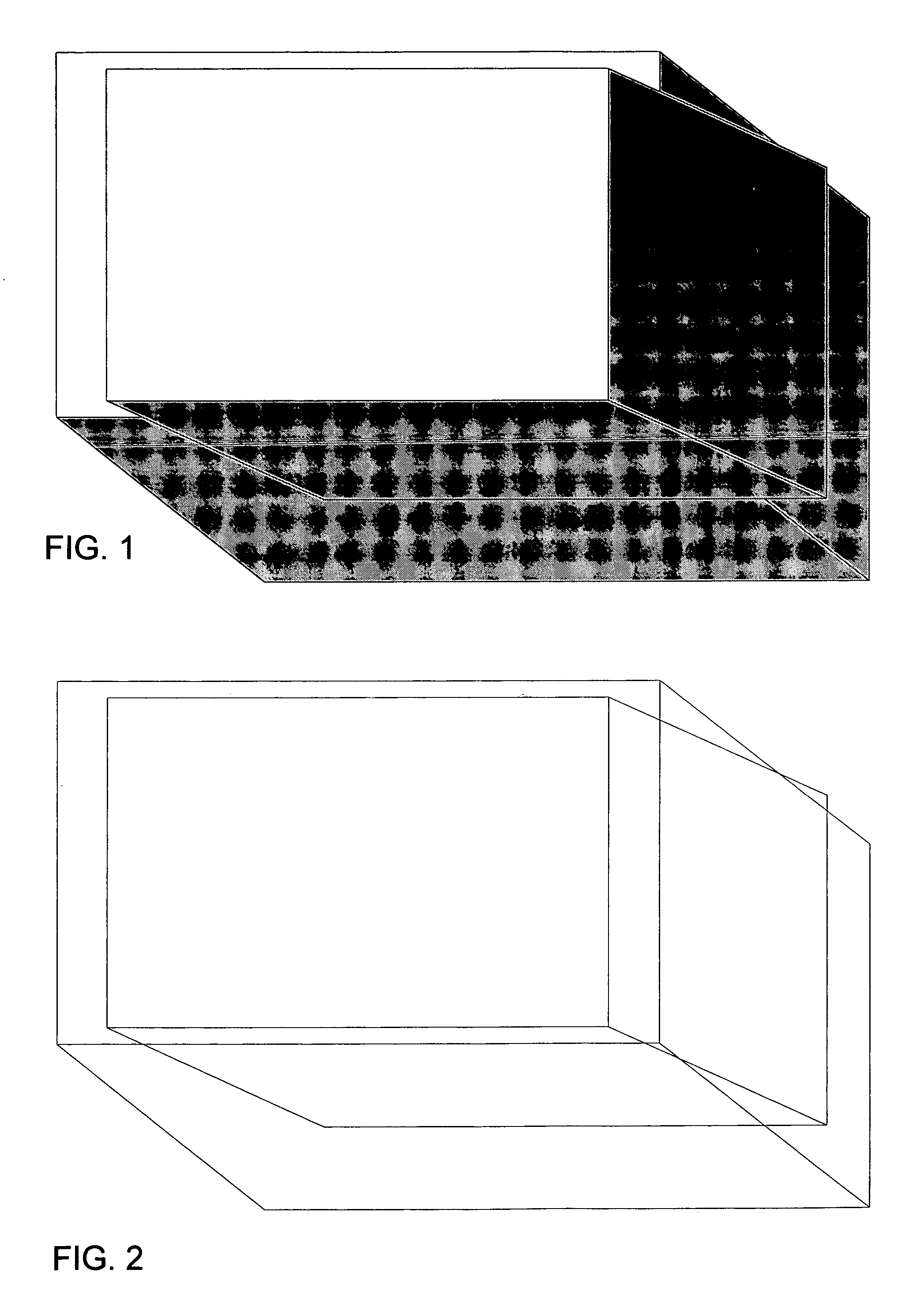
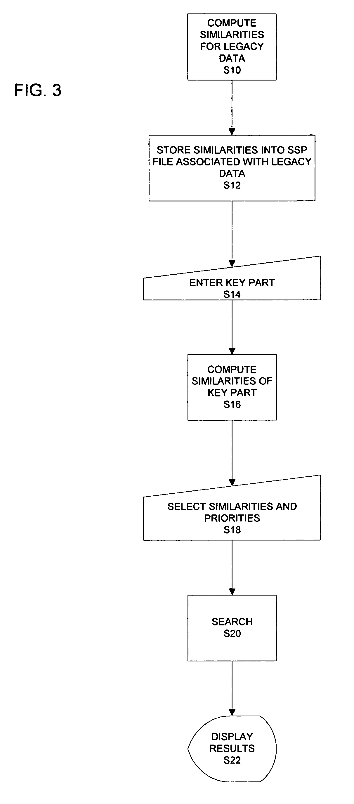
[0036]The present invention is directed to identifying patterns in sheet metal part shapes. The identified patterns can be used for searching sheet metal part models stored in a database.

[0037]An object of the present invention is to recognize patterns in sheet metal part shapes. Such patterns can be recognized by a variety of types of analysis. In one embodiment, a moment of inertia is applied to the sheet metal part to determine a characteristic of the part. Other types of analysis can be used to determine additional characteristics (i.e., feature vectors) of the sheet metal part. A user can specify multiple characteristics for a part, and thus, capture a view of the user.

[0038]By observing the different characteristics of the sheet metal shapes, a search engine specific to searching sheet metal part shapes can be defined. To overcome the ambiguity of previous search methods for 3D shapes, an aspect of the present invention incorporates dual dimensional feature extraction. Dual di...


PUM

PropertyMeasurementUnit
sizeaaaaaaaaaa
shapeaaaaaaaaaa
weightaaaaaaaaaa

Abstract

Analysis is performed on sheet metal products to determine characteristics (or feature vectors) of the sheet metal products. Multiple feature vectors can be obtained for each sheet metal product. Exemplary analyses include a first order moment and a second order moment. The characteristics can be compared with characteristics of other sheet metal part shapes to determine how similar the shapes are.

Description

BACKGROUND OF THE INVENTION[0001]1. Field of the Invention[0002]The present invention relates to the field of computer-aided design for sheet metal parts. More particularly, the present invention relates to recognizing patterns in sheet metal parts.[0003]2. Background Information[0004]The ability to recognize patterns in sheet metal parts would be useful. One use for pattern recognition is searching for similar parts. When designing a new 3D object (i.e., target object) on a computer-aided design (CAD) system, it is sometimes more efficient to start with a similar object and modify the similar object to create the desired object, rather than to design the new object from scratch. In order to start with the similar object, a user searches for an object having some type of similarity to the target object.[0005]Many attempts have been made to find geometrical similarities of 3D solid objects. None of the previous attempts, however, have succeeded in recognizing patterns of sheet metal ...

Claims


Application Information

Patent Timeline
Patent Type & Authority Patents(United States)
IPC IPC(8): G06F19/00G06V10/424
CPCG06K9/525G06K9/4685G06V10/424G06V10/435
Inventor SAKAI, SATOSHIISHII, MASANOBU
Owner AMADA CO LTD
Learn More